All pins have the save voltages as measured at the board for the modules using the filter caps as reference ground.
It is not. A couple pages back I posted a diagram of three transistors that are on this board and their configuration. I have since removed all three and bench tested them and they all test fine. The schematic I drew and posted is as close to the diagram as it gets.
If you're referring to post 175, that's insufficient. It shows no connections to anything, no resistors/resistor values, essentially nothing.
Agreed that wasnt probably the most useful schematic. I mostly drew it to show the arrangement of the transistors in the circuit. I will hand draw one this week to cover that area. Not sure if it matters, but I have removed and bench tested every transistor on the audio board and they all test ok. Thanks again for your patience with me.
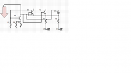
Ok, this took a bit. Not sure how far out in which direction I should go here. Is this helpful? the big arrow is ground for both rails (the one with the filter caps on it we have been using as reference when checking square wave)
q1 (q608) a733 PNP
q2 (q602) c945 NPN
q3 (q603) c945 NPN
r1 11k
r2 1.2k
r3 100k
c1 10v 100mf
r4 27k
r5 27k
st1 left speaker output pos
st2 right speaker output pos
q1 (q608) a733 PNP
q2 (q602) c945 NPN
q3 (q603) c945 NPN
r1 11k
r2 1.2k
r3 100k
c1 10v 100mf
r4 27k
r5 27k
st1 left speaker output pos
st2 right speaker output pos
Attachments
Why didn't you use the right designations on the diagram?
mF should be uF unless it's a huge capacitor.
That circuit appears to be the DC offset protection. You could remove those transistors and the amp would work normally. Try reconnecting the SCR gate and removing these one at a time, starting with Q1 to see if the amp shuts down.
mF should be uF unless it's a huge capacitor.
That circuit appears to be the DC offset protection. You could remove those transistors and the amp would work normally. Try reconnecting the SCR gate and removing these one at a time, starting with Q1 to see if the amp shuts down.
I didnt know how to make the special character for "micro", so i thought "m" would suffice. sorry, Im glad you understood it though.
I reconnected the gate leg of the SCR and removed Q1. Problem is no longer present and it maintains square wave signal.
I reconnected the gate leg of the SCR and removed Q1. Problem is no longer present and it maintains square wave signal.
the only relay for the amp is the one for 2 speaker vs 4 speaker. When powered up, yes it will switch when I push the button. Rail voltage goes from 33vac to 26vac when I depress the button. All tests have been performed with button out placing it in two speaker mode.
if that is of any import.
if that is of any import.
OK. Do you read any DC voltage across the two terminals for any channel?
Try with the switch in both positions.
Try with the switch in both positions.
If meter probes are polarity matched to the speaker outputs, both channels have +2.1vdc. Switch position makes no change in readings.
Short each pair of terminals with a wire. Power the amp up. Is there any significant current draw (more than what it previously drew)?
Well, I dont have my 87 meter here so I cant check current. I did check voltage and it is the same at 33.4vac with terminals shorted. Did this with both channels and nothing that indicates to me any big jump in current draw. Then again, I dont have an ammeter on it.
Q1 reinstalled, jumpers left in place. No rail voltage on either side.
Incidentally, prior to reinstalling the gate leg on the SCR, I did verify rail voltage. Then installed the gate leg and verified no rail voltage. Then after removing Q1, verified rail voltage.
Seems like the same result with jumpers in or not in when Q1 is installed.
Incidentally, prior to reinstalling the gate leg on the SCR, I did verify rail voltage. Then installed the gate leg and verified no rail voltage. Then after removing Q1, verified rail voltage.
Seems like the same result with jumpers in or not in when Q1 is installed.
- Home
- General Interest
- Car Audio
- A/D/S power plate 80 and 100