Ok, back at it. Had to take a break as I think I was getting lost. I also found that my connections werent the greatest. So, light bulb on both sides lights up and have about 32v at the bulb.
I connected the pos rail wire to the audio board and lost that voltage. still had neg rail voltage.Desoldered pos rail and voltage did not return. also, neg side was down to 23v and dropping. Removed power from amp and waited about 30 seconds, and now I have both pos and neg rails back.
When I lost the pos rail, I checked voltage in AC across the collectors of the PS transistors and had 66vac. When its all working properly, the transistors have 13v. Sorry this is pretty confusing.
reviewing the schematic, it might be noted that this amp isnt the exact same. Tehre is a 2 speaker and 4 speaker button on it. This will activate a relay on the PS board. Im not sure how that works.
You need to leave the scope constantly connected to the collectors. The supply could be shutting down intermittently and you wouldn't know if you don't leave the scope on the collectors.
How many speaker terminals are there on this amp?
How many speaker terminals are there on this amp?
Ok, will do that when I get home.
There are only four speaker binding posts on the amp. So, I suspect maybe the "four speaker" part is presuming increased impedance due to putting two speakers on one channel?
There are only four speaker binding posts on the amp. So, I suspect maybe the "four speaker" part is presuming increased impedance due to putting two speakers on one channel?
ok, since scope is only single channel, I could only keep it connected to one side. powered amp up, verified both pos and neg rail. voltage at collectors is 13.4vac with good sine wave. Keeping scope connected to one collector, then touched pos rail wire to audio board. sine wave turns really really noisy and voltage goes to 55vac. took lead off of one collector and tested the other collector with the same readings.
Before or after I connect the pos rail wire to the audio board? I get a really clean sinewave before. After that, I get almost nothing. Meter must have autoranged regarding my previous as I just went to grab some pics of what I am seeing and im getting 5vac and noise after I connect it. First pic is with rail wire not connected, second pic is with it connected. It will recover if the wire isnt left on too long. If its left on longer than say 20 seconds, it doesnt go back to a sinewave or 13vac. REmove power for ten seconds and reconnect and it wont recover to a proper waveform. Waited about a 35 seconds and reconnected and everything looks good again
Attachments
![DSC_1661[1].jpg](/community/data/attachments/810/810864-2c475ba438fc07f0ccfc611576d89701.jpg?hash=LEdbpDj8B_)
![DSC_1662[1].jpg](/community/data/attachments/810/810888-5bd99a2438f6a666d1189537cc3d77a6.jpg?hash=W9maJDj2pm)
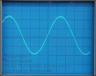
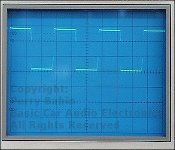
What I was initially referring to as a noisy since wave did look like what is in the left picture. This is also when I swear the meter was reading 55v. I attempted to replicate this to take pictures after I posted and after three repetitions, I concluded the meter had automatically changed its range. I could not replicated this after doing the same test three times.
The scope should virtually always be in manual mode and DC coupled.
You have to go back through the tests and determine if the supply is running or not when you lose the positive rail.
If it stops every time you touch the positive rail to the audio board (check with the lamp in series and direct), we'll have to try to determine whats causing it.
Could you have a solder bridge between any of the pads of the audio modules?
Ok, from the tests I did last night, the latter scenario is what was consistent during multiple replications of the same scenario of having the scope DC coupled and on the collectors. the moment I touched the pos rail wire to the audio board, power dropped out. If i immediately removed the wire, it would recover. If I waited, it would not recover without removing power for a little bit.
I will redo this test tonight with the light bulb and see if teh results change.
I will also double check the pads for the ICs and see if there is maybe something shorted there too.
I will redo this test tonight with the light bulb and see if teh results change.
I will also double check the pads for the ICs and see if there is maybe something shorted there too.
pads have no shorts between them. light bulb test keeps power supply going with no change in votlage or square wave. Double checked again by putting pos rail wire on audio board and voltage dropped out along with the square wave.
So, I am looking at the schematic and judging by the results, I think there seems to be something with a short on the pos rail side. Neg rail side does not exhibit these symptoms. I was thinking about desoldering each component along the way to pin 1 of the IC to see if that stops it. First two are caps. One appears to be a large tantalum and the other a radial aluminium. Do caps short? Testing resistance between the ground for the rails and pos and neg sides, I get about 4m ohm on the pos side when testing resistance (amp off) as opposed to open circuit on the neg side. So, I am concluding there is an issue on the audio board still on the pos rail side. I am also concluding that the output from the PS board is acceptable since it lights up the bulb as well as maintains square wave and voltage.
Tantalum caps, especially older ones, tend to short.
Did the lamp light when it was in series with the positive rail?
Did the lamp light when it was in series with the positive rail?
Ok, maybe thats an issue with the caps. Are there visual tells like electrolytic cap failures? Or is it more of a desolder and check with an ohm meter?
Bulb test was done with pos rail wire not connected to audio board, one side of bulb connected to the ground for the rails and the other to the pos rail side on the PS board. I tested both rails with the bulb this way and both sides behaved the same.
I think since the bulb test didnt show anything different between the two sides, we have a problem on the pos rail side of the audio board, right? I might also not, when touching the pos rail wire to the audio board, there is a spark, and I can head the power supply pick up in load too. Neg side rail does not do this.
I asked that you insert the lamp in the positive rail between the two boards to see if the supply would remain on.
Electrolytic caps aren't known for shorting like tantalum caps. They typically leak and cause damage to the board or lose value. Sometimes, they physically come apart or swell up.
Electrolytic caps aren't known for shorting like tantalum caps. They typically leak and cause damage to the board or lose value. Sometimes, they physically come apart or swell up.
Sorry, I didnt interpret correctly. Putting the bulb in series between the PS board and audio board in series did not light up the bulb, nor did the PS transistors lose voltage or square wave. Stayed constant. To double check, I then touched the pos rail wire to the audio board and it did the same as the previous tests and dropped voltage, after arcing.
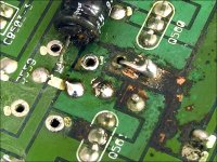
regarding leaky caps, there is a little bit of residue on the board. Im not familiar enough with leaky caps to know that might be solder rosin if thats a thing, or electrolyte on the board. I have included a pic to try and get you an idea of what I see. It may be nothing, or it may be something. None of the caps look suspect though. You can see at the leads for CR601b little halos where they pass through the board. Most of the components on this board have this along with some othe random spots. Not sure if thats a concern or not.
regarding leaky caps, there is a little bit of residue on the board. Im not familiar enough with leaky caps to know that might be solder rosin if thats a thing, or electrolyte on the board. I have included a pic to try and get you an idea of what I see. It may be nothing, or it may be something. None of the caps look suspect though. You can see at the leads for CR601b little halos where they pass through the board. Most of the components on this board have this along with some othe random spots. Not sure if thats a concern or not.
Attachments
![DSC_1667[1].jpg](/community/data/attachments/813/813158-20628aa41551c6540664fb10938f7670.jpg?hash=IGKKpBVRxl)
All of the components have that. It's likely flux that came through from the bottom.
When electrolytic caps leak, it's generally obvious. The electrolyte is both corrosive and conductive. The image below shows where the board was damaged from a leaking cap.
Did you remove the tantalum cap to check it?
When electrolytic caps leak, it's generally obvious. The electrolyte is both corrosive and conductive. The image below shows where the board was damaged from a leaking cap.
Did you remove the tantalum cap to check it?
Attachments
I have not removed it yet. Just a basic ohm test I presume and watch the value gradually change?
I do have an Alpine amp I just got that has leaky caps and its glaringly obvious the leakage on that one.
I do have an Alpine amp I just got that has leaky caps and its glaringly obvious the leakage on that one.
tantalum removed. ohm tested like a normal cap showing value gradually changing. Same symptoms. Electrolytic next or maybe remove q602b next and see what it does?
- Home
- General Interest
- Car Audio
- A/D/S power plate 80 and 100