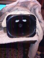

Oh balls to it, who needs sleep. Right here is PIC of measurement set up. Less than ideal I appreciate. Mic at 100cm in photo.
Nice.
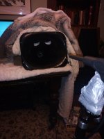
Looks like a character from Star Wars or a WW1 gas mask 🙂
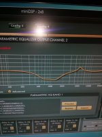
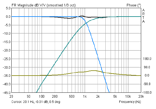
Eq graphs to give you an idea of how I am Eq ing flat.
That's a of EQ for the woofers but then you are trying to account for all that open back blanket business. In a sealed box it should follow the sim quite closely and you will gain back your sensitivity and have auto flatness for the most part.
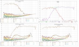
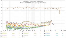
I just repeated the distortion tests - here is a montage for you. I think there is no doubting the very low distortion in the woofer - it must be a result of the band-pass taps. I have built many speakers and not seen anything as good as this.
There is nothing wrong with those measurements. Argue all you like - you can clearly see they have been taken together and the SB65 full range driver makes a nice control.
There is nothing wrong with those measurements. Argue all you like - you can clearly see they have been taken together and the SB65 full range driver makes a nice control.
Attachments
Finally - so hopefully I can go to bed!
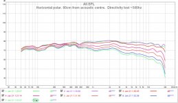
Here is a more accurate set of horizontal polars - all measured! Directivity is lost around 500hz which is correct for the horn specs. Just shows how inaccurate 'freehand' is, but I was only doing quick and dirty measurements first to look at the CD up top.
Here is a more accurate set of horizontal polars - all measured! Directivity is lost around 500hz which is correct for the horn specs. Just shows how inaccurate 'freehand' is, but I was only doing quick and dirty measurements first to look at the CD up top.
Attachments
Last edited:
Thanks for the last set of plots. I have to say that the data is the data - especially if your mic is calibrated to absolute SPL and you have shown it is at 1m. The sims were showing a very low cone excursion at 2.83v of only 0.75mm. But that was with a sealed back. It's not unimaginable to believe that a high quality woofer operating at about 10% of linear excursion can't have -50dB HD.
Yes it is the bandpass ports and horn working together to do this. Very cool - and since you mention that you know this is special compared to most speakers - I tend to think you have it right.
Thanks for redoing polars more carefully. That looks better.
Good night - you deserve a rest after a big day like today.
Last edited:

Nice X - I think you are going to be getting better results than me, giving my throat adapter was done with some epoxy putty and freehand routing!
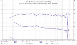
Right what shall we work on today? Shall we get the phase sorted? Given this 'Fast Synergy' has excellent point source behavior, getting the phase sorted too should give us some nice results!
Right what shall we work on today? Shall we get the phase sorted? Given this 'Fast Synergy' has excellent point source behavior, getting the phase sorted too should give us some nice results!
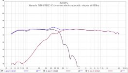
Have you read up on Harsch XO? Set the electrical lowpass on the woofer such that the electroacoustical slope is -24dB/oct Butterworth at 500Hz, I may even go 600Hz to get away from the SB65 distortion hump. Then set the electrical high pass on the SB65 such that the electroacoustical slope is -12dB/oct on the high pass. In practice I find that using BW24 LPF on woofer works well and BW6 HPF on SB65 will get you the -12dB/oct Bessel. Then adjust time delay so that tweeter is behind woofer by half a period of the XO frequency (assuming both drivers have no acoustic center offset). Given that the tweeter is already set back behind the woofer, you may need less. Both drivers positive polarity. The summation, when done right will drop about 1.5dB below the woofer only but then come up and flatten out. The phase will be flat about zero degrees with a 55deg hump at XO frequency.
You won't have any phase wrap and the time alignment of the tweeter will be at the leading edge of the woofer, and both will be positive.
http://www.diyaudio.com/forums/multi-way/277691-s-harsch-xo.html
You won't have any phase wrap and the time alignment of the tweeter will be at the leading edge of the woofer, and both will be positive.
http://www.diyaudio.com/forums/multi-way/277691-s-harsch-xo.html
Last edited:
Thanks X - will get on it now. Will report back shortly. I will do a measured vertical polar as well for completeness.
Nice X - I think you are going to be getting better results than me, giving my throat adapter was done with some epoxy putty and freehand routing!
We will see, my printer has been acting up lately so who knows how good the prints will come out. They won't be shiny and polished like yours though.
Bushmeister, excellent measurements I thought you might have had some cancelations from the unequal distances between parts of woofer cone and your ports but they don't seem to be there which is great.
When you get your mic out it would be interesting to see how well the full range and woofer are time aligned just through their physical offsets by doing a reverse null measurement on the crossover.
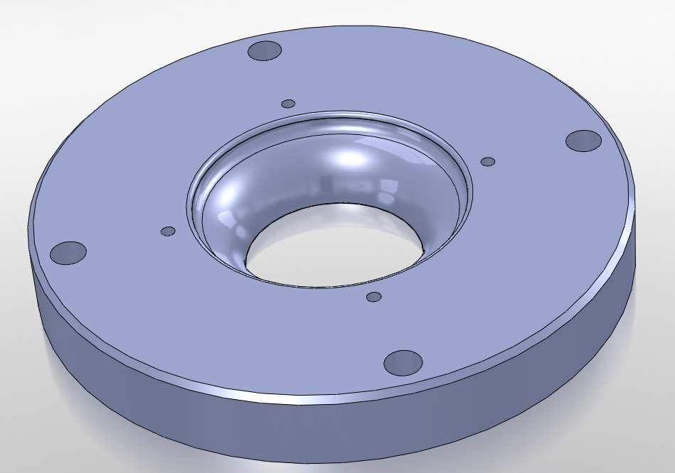
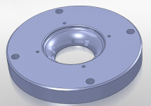
X, having seen how the Faital horn mounts it seems you could get a very nice throat adapter by using a disc of acrylic to replace the steel and rout the same round over into the entrance hole as you have in your CAD diagram. If you want it very smooth then use a mapp gas torch to 'flame polish' the edge.
If you have a router and a disc of acrylic I would think this could be knocked up in a very short time.
When you get your mic out it would be interesting to see how well the full range and woofer are time aligned just through their physical offsets by doing a reverse null measurement on the crossover.
X, having seen how the Faital horn mounts it seems you could get a very nice throat adapter by using a disc of acrylic to replace the steel and rout the same round over into the entrance hole as you have in your CAD diagram. If you want it very smooth then use a mapp gas torch to 'flame polish' the edge.
If you have a router and a disc of acrylic I would think this could be knocked up in a very short time.
I am printing the adapter now. By the time I wake up it should be done. Hopefully if the filament doesn't tangle. I can sand and polish the printed throat to a certain extent.
When you get your mic out it would be interesting to see how well the full range and woofer are time aligned just through their physical offsets by doing a reverse null measurement on the crossover.
.
Rather than doing a reverse null - I use a technique described here:
Refining a 4-way open-baffle speaker with the miniDSP 2×4
Essentially you do it like this:
Time-alignment of drivers
There are various ways of working out what to set the time delays to, but here’s a fairly quick and simple technique:
Pick a pair of drivers, and place the microphone vertically mid-way between the centers of the drivers, and about a meter away.
Turn off all channels except those two.
Turn off the crossover filters for those two drivers.
Set one driver to have a short (1 to a few ms, depending on the drivers) time delay.
Run a sweep over a frequency range that is covered by both drivers.
Look at the impulse response to determine how much the drivers differ from the specified time delay.
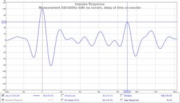
Using this techique I have discovered - purely by serendipity that the woofer taps and horn have almost perfect physical offsets for time alignment.
Here is an impulse response with 9ms delay added. You can see it is bang on 9ms.
Attachments
That is a very good technique that I hadn't seen before. I've read most of the articles on that site but must have missed that one.
I mainly thought the reverse null would be easy to show the alignment with only having to flip polarity in minidsp but you already went one better!
Can't wait to see how these turn out when they are all finished!
I mainly thought the reverse null would be easy to show the alignment with only having to flip polarity in minidsp but you already went one better!
Can't wait to see how these turn out when they are all finished!
Rather than doing a reverse null - I use a technique described here:
Refining a 4-way open-baffle speaker with the miniDSP 2×4
Essentially you do it like this:
Time-alignment of drivers
There are various ways of working out what to set the time delays to, but here’s a fairly quick and simple technique:
Pick a pair of drivers, and place the microphone vertically mid-way between the centers of the drivers, and about a meter away.
Turn off all channels except those two.
Turn off the crossover filters for those two drivers.
Set one driver to have a short (1 to a few ms, depending on the drivers) time delay.
Run a sweep over a frequency range that is covered by both drivers.
Look at the impulse response to determine how much the drivers differ from the specified time delay.
Using this techique I have discovered - purely by serendipity that the woofer taps and horn have almost perfect physical offsets for time alignment.
Here is an impulse response with 9ms delay added. You can see it is bang on 9ms.
That's how I find my sweet spot in my measurements. But, you have to be careful. The peak shown in an impulse measurement which is displayed by REW is showing a relatively high frequency peak. You've got to be sure that both of the drivers are actually capable of outputting energy there. For instance if the woofer cuts out at 4 KHz it's peak won't resemble the same frequency as the tweeter. Globally speaking you'd be alright. You might turn on a filter on the filtered IR tab, say 2 KHz 1/3 octave and go back to the IR tab, what does it look like now? Both drivers will now show the results filtered at exactly the same frequency. It won't look like a small impulse peak anymore though.
- Home
- Loudspeakers
- Multi-Way
- A Bookshelf Multi-Way Point-Source Horn