That alignment is perfect indeed. How much clearance does the surround have before touching the WG flange base?
Following this with interest. Have I missed something or have you machined out the end of the waveguide to match the 2.5" driver?
Yes - if you look back earlier in the thread there are pictures! I use a router, then sanded, then polished to get a high finish.
That alignment is perfect indeed. How much clearance does the surround have before touching the WG flange base?
About 3mm. That's another reason I modified the driver bezels with epoxy putty. It allowed me to very accurately lift the surround up 2mm all around, then with gasket, it is currently sitting 3mm above flange.
Also I have sanded and polished the rim of epoxy too, so it is a very smooth transition from bezel to flange.
I don't think you could have done a better job on the driver to WG mounting and transition. Now we just have to wait for your measurement laptop to come back from repair.

The woofers are in! Those look like a really nice basket and frame. Can you get an oblique closer up photo so I can see the detail of how frame and bezel might mount?
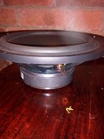

Don't worry - that is just an MDF mock-up ring, I am planing to make some up from 12mm ply with my router.
As you can see, the woofers are pretty shallow for 8 inchers - which works out well, keeping it all compact.
As you can see, the woofers are pretty shallow for 8 inchers - which works out well, keeping it all compact.

Scratch that idea!! Much easier to have a square piece, route out a ring and just build up the epoxy filler under the areas of the two red circles......
That driver size is a perfect match for available real estate on horn wall. This is looking really integrated like it was designed that way. I like how compact the woofers are and when mounted to baffle boards sitting on side of horn the overall profile still manages to stay very compact. Certainly much smaller than a flat baffle WHW layout would be.
Thanks for the closeup photos!
Thanks for the closeup photos!
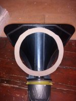
Bushmeister,Like this:
PS The back chamber looks wonky because it isn't screwed on tightly. (And that outer covering is some damping sheet I had left over from a previous product - inside is felt/damping/rock-wool).
Putting the 8" ports that near the mouth will make the center to center distance quite wide. Ideally they should be within 1/4 wavelength if you want smooth side to side polar response, for a 1500 Hz crossover the center to center distance between the ports should be only 2.26". Obviously, with a 1.4" throat exit, that won't happen, but the closer the exits to the throat (reducing C to C distance), the smoother the midrange response.
That said, the more disruption at the throat, the rougher the HF response, though a 2" dome VHF dispersion won't cover the outside portion of your horn, so I would be more concerned about the mid port center to center distance, and convergence at the crossover point.
Art
Last edited:
Weltersys,
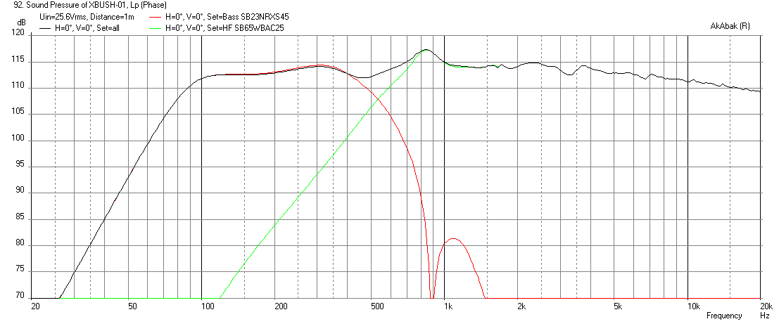
The XO is 500Hz or 13.5in 1/2-wave and 6.75in 1/4-wave so I think the location of ports is fine just as predicted in model. If XO was 1500Hz - that's another story and requires ports as close as you can get to throat like a conventional synergy/unity design. This is really a horn based FAST.
Predicted response with ports 10cm from mouth plane.
Last edited:
Hi Art - thanks for the advice!
The crossover point it going to be 400-500hz most likely, so 1/4 wavelength is about 20cm or 8 inches. The C-C distance on those ports are 16cm - measured along the inside of the horn, so should be well within 1/4 spacing.
The crossover point it going to be 400-500hz most likely, so 1/4 wavelength is about 20cm or 8 inches. The C-C distance on those ports are 16cm - measured along the inside of the horn, so should be well within 1/4 spacing.
Ha. Ha X - we cross posted! Great minds!
Although - one of us has done the maths wrong! Isn't 13.5inches 1/2 wavelength at 500hz?
Although - one of us has done the maths wrong! Isn't 13.5inches 1/2 wavelength at 500hz?
That driver size is a perfect match for available real estate on horn wall. This is looking really integrated like it was designed that way.
Dude! It was designed that way!! I spent ages measuring the horns and looking up driver diameters! It is not a coincidence that they fit perfectly!!!😀
Ha. Ha X - we cross posted! Great minds!
Although - one of us has done the maths wrong! Isn't 13.5inches 1/2 wavelength at 500hz?
I was still typing and generally set the spacing within range of 1/4 wave to 1/2 wave. Sometimes people use single value of 1/3-wave as a goal.
Yes, 6.78" C to C would be 1/4 wavelength at 500 Hz.Ha. Ha X - we cross posted! Great minds!
Although - one of us has done the maths wrong! Isn't 13.5inches 1/2 wavelength at 500hz?
I didn't realize you were planning to cross the little full ranger so low, should have looked closer before posting.
Art
Last edited:
Dude! It was designed that way!! I spent ages measuring the horns and looking up driver diameters! It is not a coincidence that they fit perfectly!!!😀
I see, you have had a serious affliction incubating all these years and the symptoms finally present themselves 🙂
- Home
- Loudspeakers
- Multi-Way
- A Bookshelf Multi-Way Point-Source Horn