Good idea Brytt!
Or I could just mount the two 8 inch woofers below the horn, C-C distance would be less than with a larger driver anyway.
But at £30 a horn - we can have a go at cutting some ports!
Or I could just mount the two 8 inch woofers below the horn, C-C distance would be less than with a larger driver anyway.
But at £30 a horn - we can have a go at cutting some ports!

I like the slots better. I bet it doesn't ruin the waveguide performance as much as you think it might - it's all about staying away from the throat and once the slots are on the outer half, much less influence.
Having horn walls with ports keeps front profile of speaker much smaller in addition to it being a point source.
Having horn walls with ports keeps front profile of speaker much smaller in addition to it being a point source.
Yes proposal is just a backdoor because horn cost is pretty good low.
Cross finger here it perform well with ports inside horn for final build.
Cross finger here it perform well with ports inside horn for final build.
I agree Xrk. I have just looked through some of the other synergy builds and danley models - large holes cut in multiple places.
Because this horn is quite narrow - 60x40, those pictures look much worse than they are - the throat and first 1/2 of the horn is untouched.
Still - soon we will have measurements of the horn and SB65, then I will start building in earnest...... Then more measuring!
Because this horn is quite narrow - 60x40, those pictures look much worse than they are - the throat and first 1/2 of the horn is untouched.
Still - soon we will have measurements of the horn and SB65, then I will start building in earnest...... Then more measuring!
Yes proposal is just a backdoor because horn cost is pretty good low.
Cross finger here it perform well with ports inside horn for final build.
Byrtt,
I still owe you sims of a band pass 12in woofer and 10F. 🙂
I agree Xrk. I have just looked through some of the other synergy builds and danley models - large holes cut in multiple places.
Because this horn is quite narrow - 60x40, those pictures look much worse than they are - the throat and first 1/2 of the horn is untouched.
Still - soon we will have measurements of the horn and SB65, then I will start building in earnest...... Then more measuring!
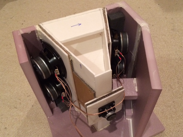
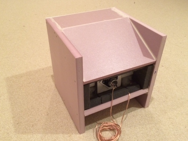
Can't wait to see the measurement - but looks like you still need to build rolled wool dagger rear chamber and mount the driver to horn. Can you use wood screws to hold driver to flange or will holes have to be drilled through and nuts and bolts used? It makes a big difference for diffraction if WG is flush mounted on similar baffle you plan to use vs free space unmounted. Which brings up the next question - have you thought about what the overall outside enclosure is going to look like?
If you look at my small Trynergy - I ended up angling the walls behind the woofers towards to back in an effort to reduce volume.
Last edited:
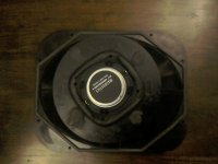
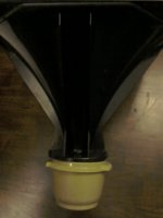
OK, for sb65 rear chamber found some old Tupperware bowls. About 3mm thick, seem innately well damped as plastic not rigid, volume of 0.8l for a sealed qtc of 0.8ish, which given our crossover at 500hz is fairly irrelevant anyway.
Nice internal hemisphere with enough room to stuff well. I think with silentcoat, felt and fibreglass these will make nice chambers.
Also perfect size to bolt onto horn with a compressible gasket for driver/stuffing modification.
Nice internal hemisphere with enough room to stuff well. I think with silentcoat, felt and fibreglass these will make nice chambers.
Also perfect size to bolt onto horn with a compressible gasket for driver/stuffing modification.
Attachments

Last edited:
Nice find with the tupperware bowl. Low density polyethylene is probably what it is made of - firm but not hard. Great fit there. I see you sealed off all bolt holes you don't need.
OK XrK - and those familiar with synergy designs....
I have been thinking about these woofer taps. Looking at those tap air velocities - it would seem there would be audible noise if we stick to approx 20% woofer SD, but looking at the Danley designs they don't appear to be concerned about this.
The SH 50 for instance will hit 130dB at 50hz and drop down to 37hz with it's two 12 inch woofers, yet the woofer taps don't appear to be bigger than perhaps 2.5-3 inches.
I wonder if the tap velocities don't matter in the same way that they do on a vented enclosure. After all - if you are injecting 130dB of output through the taps, how are you going to hear any chuffing through them?
Just thinking out loud here...
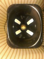
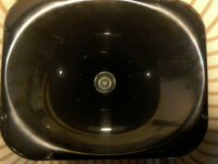
 Sb65 mounted.
Attachments

Last edited:
Some people like to stick below 10m/s to be absolutely safe from chuffing. That's a really conservative number. It also depends on how smooth the duct walls are and whether or not you have sharp corners. It is basically wind noise and turbulence you are trying to avoid. There are also other limits like trying to keep velocity well below Mach 0.1 to avoid effects of compressive flow. Mach 0.1 limit is much higher than 10m/s, and for air at room temperature is 34m/s. So perhaps in case of pro sound design they are using something like 30m/s as top end for port velocities?
Finally, if you want to look at avoiding turbulent flow through the ducts, calculate the Reynolds number for the characteristic dia of the flow and keep Re <2300. This limit is extremely low and not really practical as most engineering flows with any power in them will be highly turbulent.
Re=UD/nu, for velocity U=10m/s, and hydraulic foam of D=0.05m, nu is kinematic viscosity of air and it about 1.5x10^-5 m2/s. You already get Re=33,000. Well into turbulent flow.
Last edited:
View attachment 524906Sb65 mounted.
Nice! What is that gold colored crinkle edge that looks like a pie pan edge? That is the sorbothane sheet with some gold foil on top of it?
Looks solid though the work you did building up driver bezel with epoxy putty.
That WG must be adding reflections because what should be a solid black dust cap on SB65 looks like there is a central silver disc then black then the aluminum cone.
Last edited:
OK. So it would seem for pro-audio use - it is likely they simply don't care too much about turbulence, because at the dB it is occurring it becomes somewhat irrelevant.
But for home hi-fi use.......
I have been looking again at the mounting of the woofers - I have just gone out and bought 2kg of epoxy filler, and my plan is to use the filler to build up the horn to make a flat mounting area, that the mounting board will then be stuck to.
I have also looked at the taps again, and whilst we both think the slots look better, I think the round holes may be better from a diffraction point of view, as they can be tapped in much further from the throat than the start of the slot will be.
I am thinking 60mm diameter circular taps, placed as far out as possible given the woofers cone area, will probably be the best compromise of factors...
Last edited:
What is that gold colored crinkle edge that looks like a pie pan edge?
That WG must be adding reflections because what should be a solid black dust cap on SB65 looks like there is a central silver disc then black then the aluminum cone.
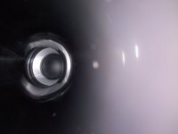
The gold edging is simple driver gasket foam - I am going to do this scientifically - so measurements first with normal gaskets, then with sorbothane! 😀
The black/silver/black/silver is an optical illusion - it's a reflection of the overhead light in the shiny surface - I will try to get a better photo. (The throat is untouched at 1.4 inches)
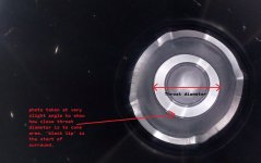
Following this with interest. Have I missed something or have you machined out the end of the waveguide to match the 2.5" driver?
Oh great photo with angle - I see where the alignment is now. That WG channels sound and does same for light reflections when viewed end on. Thanks for the photo - looks great and I have a feeling it looks very smooth at the radiused transition to the half roll surround. This may work very well right off the bat. Based on how smooth the lip is, the first characteristic cancellation dip may correspond to the diameter of the sealing gasket right beyond the surround diameter. Assuming that is 1.6in dia you may get a first cancellation dip at 8.5kHz. Not too bad because above main telephone band of 600Hz to 6kHz. We will see.
Last edited:
- Home
- Loudspeakers
- Multi-Way
- A Bookshelf Multi-Way Point-Source Horn