Yup I reckon this version would create more problems than it hopes to solve, but the only way to learn fusion and 3d printing is to try progressively harder ideas.
I'll save the filament for something else though
I'll save the filament for something else though
Nice work! I think you can add 10% support matrix and infill to the void and let that act as the “stuffing”. It will serve as the support the structure and as the damping material. To do it just add a very thin solid wall that you can perforate later and peel off.Being a sucker for punishment, I decided to stay up late and see if I could actually model a fibonacci spiral back chamber.... turns out you can! (+/-10%)
I will buy anybody a very large beer at the pub if they can work out how to 3D print this. 😉
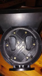
Ps. Notice the pockets in the adaptor, plan would be to stuff with absorption.
Pps. Change .txt to .f3d
View attachment 1217001View attachment 1216992View attachment 1216993View attachment 1216994View attachment 1216995
Maybe all this effort is better spent on the other side of the cone? I wonder what a 3D-printed phase plug would do for the response.
https://www.diyaudio.com/community/threads/diy-compression-drivers.317125/
https://www.diyaudio.com/community/threads/diy-compression-drivers.317125/

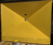
A 5 sided pyramidal back chamber filled with fiberglass (aka “Dagger”) rear chamber works very well. This is more compact and cooler technology though.
Benefits of absorbing the rear wave is less muddy sound for more clarity because the back wave doesn’t interfere with the front wave by bouncing off chamber and coming back out the front. It sounds like an open baffle speaker but it’s not.
Benefits of absorbing the rear wave is less muddy sound for more clarity because the back wave doesn’t interfere with the front wave by bouncing off chamber and coming back out the front. It sounds like an open baffle speaker but it’s not.
I think I get it, although I just had another idea to flip the spiral so the rear of the drivers cone fires down the axis of the spiral... More soonNice work! I think you can add 10% support matrix and infill to the void and let that act as the “stuffing”. It will serve as the support the structure and as the damping material. To do it just add a very thin solid wall that you can perforate later and peel off.
View attachment 1217186
I may look at it once I get the woofers and sb65 mounted and working. All these parts are being designed and printed to be modular and interchangable so I can explore concepts and do back to back measurments later.Maybe all this effort is better spent on the other side of the cone? I wonder what a 3D-printed phase plug would do for the response.
https://www.diyaudio.com/community/threads/diy-compression-drivers.317125/
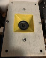
New adaptor printed, much easier to get exact alignment to the horn throat without the driver in the way.
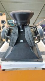
New flared rear chamber being printed now... only 6 hours to go!
will try and take some measurments tomorrow.


New flared rear chamber being printed now... only 6 hours to go!
will try and take some measurments tomorrow.
Back chamber printed, a touch on the large side me thinks. 0.69 litres
I have designed a 0.45 litre version, will print and test both.

I have designed a 0.45 litre version, will print and test both.
Cool. How did you do the internal support matrix infill? Or it sit hollow and stuffed with fiber/wool etc?
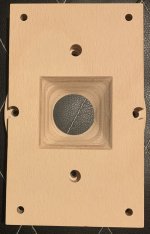
Its axactly this print, with Dacron stuffing for now.A bit of work on the rear chamber for the SB65.... Although the volume now comes in at 0.7litres which may be unnecessarily large with 500hz + XO
View attachment 1216228View attachment 1216229
Alignment lugs work well, still need to test the new throat curve for cone surround clearance at xmax
Got some new models coming of the H280 Horn and the modular woofer injection ports, just wondering if I start a new thread...?
Last edited:
If you ever think about printing your own horns, the long running ATH thread is a must visit!
There's even some Synergy/Unity variants made with that crazy cool ATH tool. Just take a look here and here to see some very cool implementations.
These horns (generated with ATH) are quite worth looking in to, making a Unity/Synergy out of them would/could be the next step.
Preferably with woofers to have a very good horizontal plus vertical pattern control.
Thanks lads, I was keeping up with ATH for the first 50 odd pages and lost track about 6 months back. It is on the books for the next horn, after I learn a bit more modelling/printing/horn skills.
Until then, I did an approximate (+/- 1degree)(+/- 1mm) model of the H280 from the outside, now I can model the woofer mounts for 3d printing.
Yes, I did have to fudge the loft from the 35mm throat to the horn walls but its not critical for this part of the exercise.
My calc tell me that I need the woofer ports to be within 172mm of the SB65 to maintain 1/4 wavelength @ 500hz. I believe I can get them as close as 145mm, at the start of the second flare in the pic.
Last edited:
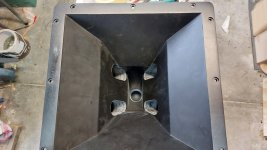
Made some headway, woofer mount for both sides printed in two parts in case I need to change Xmas clearance or port size.
Notice the m6 bolts clamping the mounts around the horn, this will take much of the woofer weight off a smaller glue/bonding area.
Next is up is die grind the woofer ports, cleanup and surface the plastics, mount everything with 3mm Eva gaskets and mount all the drivers.
Then fire it all up without enclosure using minidsp 2x4 and 4xTPA3255.
Attachments

I am now wondering if it would be easier to simply cnc a plywood horn throat, say 90% of the horn, and print only the throat with the transition from round to rectangle...
I learnt a lot, which was my primary intent, so nothing wasted.
Some REW tests hopefully during the week...
I learnt a lot, which was my primary intent, so nothing wasted.
Some REW tests hopefully during the week...
- Home
- Loudspeakers
- Multi-Way
- A Bookshelf Multi-Way Point-Source Horn