Hi @Sasha KC83,
I have just tried the stereo sub approach so far. I have "subwoofers" set up like shown in this picture. Each black cab has two Satori WO24Ps. Both drivers are connected in parallel per side and are low passed at 60Hz. I have a big L-shaped room and what you see below is the shorter part of the "L" where the speakers are set up.
The next two subwoofers are the 15inch ones at the bottom of the mains facing the backside.

I haven't tried DBA yet mainly because I haven't been able to determine the positioning of these subs for that.
I might have to do some Akabak/ABEC simulation based on room dimensions before I try anything related to DBA to at least understand what I can get and then figure out the impact of the furniture with real measurements. Since I haven't been able to set up even simulations yet, DBA is pending.
I have been puzzled by that 200Hz hole. Whatever I do elsewhere in the room other than the ceiling, it is there. For that and the 900Hz hole, I have seen that their location and depth are affected to some extent by the ceiling reflections (based on experiments I did with some amount of absorption near the ceiling area). I do see from (a very incomplete/inaccurate) modeling of the room in REW that there is potentially a combination room modes in the 200 to 220Hz region in my room as well. This along with the ceiling reflections maybe causing that hole in the 200ish Hz region

I have just tried the stereo sub approach so far. I have "subwoofers" set up like shown in this picture. Each black cab has two Satori WO24Ps. Both drivers are connected in parallel per side and are low passed at 60Hz. I have a big L-shaped room and what you see below is the shorter part of the "L" where the speakers are set up.
The next two subwoofers are the 15inch ones at the bottom of the mains facing the backside.
I haven't tried DBA yet mainly because I haven't been able to determine the positioning of these subs for that.
I might have to do some Akabak/ABEC simulation based on room dimensions before I try anything related to DBA to at least understand what I can get and then figure out the impact of the furniture with real measurements. Since I haven't been able to set up even simulations yet, DBA is pending.
I have been puzzled by that 200Hz hole. Whatever I do elsewhere in the room other than the ceiling, it is there. For that and the 900Hz hole, I have seen that their location and depth are affected to some extent by the ceiling reflections (based on experiments I did with some amount of absorption near the ceiling area). I do see from (a very incomplete/inaccurate) modeling of the room in REW that there is potentially a combination room modes in the 200 to 220Hz region in my room as well. This along with the ceiling reflections maybe causing that hole in the 200ish Hz region

^multiple reflections piling up perhaps, because there is rarely big dip just from one reflection because there is always multiple reflections and the other ones fill in, unless they happen to align and make one big dip. Ceiling reflection could be the main dip there, which some other reflections enhance.
You could try to figure out which one it is by playing with sims as you've already been doing. Ceiling is usually so far a way, in a small room, that it makes the longest early reflection and thus the first interference dip lowest in frequency of all early reflections. Since you positioning is lopsided to the room your right side reflection or something behind listening spot might be quite long as well. Front and back wall reflections have surprisingly long path length as well due to roundtrip.
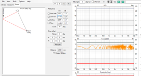
Quick try on vituixcad room tab with single ideal driver let's you checkout path lengths and resulting interference pattern fast. I see your room height is relatively tall so first interference dip, that's the widest one, get's way below 200Hz. Guestimated listening distance and driver height second interference dip could hit about at 200Hz. You could use any of the boundaries available to scout all of your first reflection points to figure out which ones have a dip around 200Hz. Move listening triangle or try to treat either or both of those somehow.

Tuning all other boundaries for 200Hz dip as well gives something like this, some of which might apply in your situation but doing this stuff yourself gives better idea what's true.


You could try to figure out which one it is by playing with sims as you've already been doing. Ceiling is usually so far a way, in a small room, that it makes the longest early reflection and thus the first interference dip lowest in frequency of all early reflections. Since you positioning is lopsided to the room your right side reflection or something behind listening spot might be quite long as well. Front and back wall reflections have surprisingly long path length as well due to roundtrip.
Quick try on vituixcad room tab with single ideal driver let's you checkout path lengths and resulting interference pattern fast. I see your room height is relatively tall so first interference dip, that's the widest one, get's way below 200Hz. Guestimated listening distance and driver height second interference dip could hit about at 200Hz. You could use any of the boundaries available to scout all of your first reflection points to figure out which ones have a dip around 200Hz. Move listening triangle or try to treat either or both of those somehow.
Tuning all other boundaries for 200Hz dip as well gives something like this, some of which might apply in your situation but doing this stuff yourself gives better idea what's true.
Attachments
Thanks a lot @tmuikku 🙂
I just did a quick sim (again) & tried based on measured distances to each boundary.
The combined big dip is a combination of reflections from different boundaries.
Here is the combined plot

Effect of front wall (surprisingly less)

Effect of left wall (Now that big broad dip is coming up)

Effect of ceiling (again the second dip coming in the 200Hz region)

Effect of floor (again a big broad dip in the 200 to 300 Hz region)

All reflections combined causes this in simulation

This is what is happening in the real world based on the left speaker measurement

I just did a quick sim (again) & tried based on measured distances to each boundary.
The combined big dip is a combination of reflections from different boundaries.
Here is the combined plot
Effect of front wall (surprisingly less)
Effect of left wall (Now that big broad dip is coming up)
Effect of ceiling (again the second dip coming in the 200Hz region)
Effect of floor (again a big broad dip in the 200 to 300 Hz region)
All reflections combined causes this in simulation
This is what is happening in the real world based on the left speaker measurement
The basic principal is quite simple. Set a delay on the rear woofers equal to the distance between the front and rear walls, invert the phase of the rear woofers and apply a level reduction equal to the sound loss by distance.haven't tried DBA yet mainly because I haven't been able to determine the positioning of these subs for that.
Tweak the delay and level up and down until you get the lowest decay and least number of nulls. But only look from 100Hz down because above that it loses effectiveness.
When your room is open on one side to a much bigger space, that bigger space will also impact the response at your listening position. Simple calculators like the REW one will have more limited value in those corcumstances.
You can get a better idea of what is happening by simulating the whole room in AKABAK and looking at the field view. There are examples with the program that can be amended. It is easier to use nodes to define the room boundaries so it can all be setup directly in AKABAK. Just read the help on how to format the nodes if you haven't used them before.
If I adjust the left wall & front wall distance along with more toe in, I can potentially get something like this

Vineeth, in room sim check how modes change when you move head vertically!!
I shifted the speakers in the room and tried this placement option

Actual measurement without & with windowing


Overall there seems to be a good correlation between what simulator predicts & what I measure.
But I have run out of options with practical placement options..
With the same crossover as earlier, it definitely sounds a bit different to my ears now but I don't know yet whether it is good or bad..
Maybe I should experiment with some EQ to pull down that broad peak centered around 500Hz by a couple of dBs and also apply some straightening based on a downward-sloping line above 1kHz.. 🙂
To think that all this hard work in designing the speakers part goes down the drain due to the room and limited placement options is sad.. 😀
Someday when I have my own house, I will have a dedicated, adequately treated music listening room for sure.. 🙂
Actual measurement without & with windowing
Overall there seems to be a good correlation between what simulator predicts & what I measure.
But I have run out of options with practical placement options..
With the same crossover as earlier, it definitely sounds a bit different to my ears now but I don't know yet whether it is good or bad..
Maybe I should experiment with some EQ to pull down that broad peak centered around 500Hz by a couple of dBs and also apply some straightening based on a downward-sloping line above 1kHz.. 🙂
To think that all this hard work in designing the speakers part goes down the drain due to the room and limited placement options is sad.. 😀
Someday when I have my own house, I will have a dedicated, adequately treated music listening room for sure.. 🙂
Last edited:
You're ~ 200hz issue certainly seem to be non-resonant SBIR effects (a couple, spaced closely), i.e. non-resonant (v resonant room modes). I am by no means an expert, but looking at your impulse and CSD/waterfall response can help determine what they are as you investigate.
I realise there is a smiley but don't be too down about the effort put into design. A good speaker anechoically is still a good speaker in a room, there will always be room effects. But if you hadn't put the effort into design you might be listening to a bad speaker with room effects and be quite unhappy.To think that all this hard work in designing the speakers part goes down the drain due to the room and limited placement options is sad.. 😀
Your brain doesn't perceive what the microphone records or the basic distance simulator shows. It is still more art than science to take those measurements and use them to improve the sound of the stock speaker. My own experience tells me it can be done but it is quite the rabbit hole to go down.
Oops, I posted having left the page up, not seeing your above posts. Yes, acoustics.... And to have an acoustically-treated dedicated room would bring it all together.
Let me know how that works out for you... 😉 It is very hard to dedicate a whole room to just listening. Even with a large house and small family, it is rare. Rooms have a way of filling up with stuff and becoming multipurpose spaces.Someday when I have my own house, I will have a dedicated, adequately treated music listening room for sure..
I agree with Fluid... The best starting point for great sound is an anechoically correct speaker. Our ear/brain can adjust to the room, we have 50,000+ years of evolution to help us "process out" the room and just hear the signal.
Perhaps your room is not ideal, but I would wager that you have better sound than 99.99% of the human population...
@vineethkumar01 I agree with the previous comments. You have a sound and scientifically designed speaker. It behaves very well and as intended. It's an achievement. As for the room, I have a couple of suggestions if you want to explore further.
Experiement#1 - Flip your woofer cabinet upside down to place the woofer near the floor. You don't need the waveguide for this, it would be too far from the woofer anyways. Measure the woofer response to see if the 200Hz dip is removed. unfortunately this does not help the current design but may indicate an alternate solution.
Experiment#2 - You could build an absorber panel, constructed like a bookshelf. It could be made with lightweight plywood, freestanding and moveable. Needs to be about 20cm deep and you could move it around or just put it in place when you need it. I would not even finish it for this experiment, as it might be disposable.
Or, as a first step, move everything in the middle of the room when your wifey is not at home, just to see (hear) what will happen and remeasure. 200 Hz problem shoudl go away...or probably appear somewhere else in freq response. But that is beauty of acoustics. Try something more symmetrical.
At this moment you can be proud that you have probably biggest nearfield monitors on Earth. 😀 With 4 15 inchers pro guys are normally organizing live concerts in not-so-small halls....
At this moment you can be proud that you have probably biggest nearfield monitors on Earth. 😀 With 4 15 inchers pro guys are normally organizing live concerts in not-so-small halls....
Thanks @fluid, @hifijim, @Bill Brown, @DonVK and @Sasha KC83 for the suggestions and comments.
I also agree that the problems in the graphs are more of a problem to the eyes than for my ears.. 😀
But i hated the room for doing this to my speakers.. 😀
Today I spent some time trying to narrow down the cause of that 200 Hz dip and I think I found it. It is the ceiling.
I placed 4ft x 2ft 20cm thick in all kinds of places I could keep them (front, back, sides, floor) in addition to two big 8ft x 2ft 20cm deep movable gobo panels. The dip seemed to remain very similar except when I placed the single 4ft x 2ft 20cm thick panel on the ceiling.. 😀
Then things started to change slightly for the better in the 200Hz region as shown below in the blue curve.

So If I am to get rid of this "problem", I need to treat the ceiling, which is a very hard thing to do due to practical issues at the moment..
So I leave that attempt here (and live with the green curve in above plot) and will move on to other things for now.. 🙂
The below is the response of the L & R speakers from MLP without FDW. if anything, I will try to slightly pull down that bump around 50hz for now

I also agree that the problems in the graphs are more of a problem to the eyes than for my ears.. 😀
But i hated the room for doing this to my speakers.. 😀
Today I spent some time trying to narrow down the cause of that 200 Hz dip and I think I found it. It is the ceiling.
I placed 4ft x 2ft 20cm thick in all kinds of places I could keep them (front, back, sides, floor) in addition to two big 8ft x 2ft 20cm deep movable gobo panels. The dip seemed to remain very similar except when I placed the single 4ft x 2ft 20cm thick panel on the ceiling.. 😀
Then things started to change slightly for the better in the 200Hz region as shown below in the blue curve.
So If I am to get rid of this "problem", I need to treat the ceiling, which is a very hard thing to do due to practical issues at the moment..
So I leave that attempt here (and live with the green curve in above plot) and will move on to other things for now.. 🙂
The below is the response of the L & R speakers from MLP without FDW. if anything, I will try to slightly pull down that bump around 50hz for now
Your brain doesn't perceive what the microphone records or the basic distance simulator shows. It is still more art than science to take those measurements and use them to improve the sound of the stock speaker. My own experience tells me it can be done but it is quite the rabbit hole to go down.
My sentiment and experiences as well.
A revealing experiment on how much the brain does to "filter" the sound of a room, is to listen to the speakers playing, but through closed back headphones few by a measurement mic. (with whatever easy to use device...I use a portable soundcard). One speaker at a time is probably best.
It's pretty amazing how different that sounds compared to listening directly to the speaker(s).
An extension of that experiment, is to record the measurement mic, and then use that recording as the listening track.
Listen to the speaker9s) normally, and see how it's getting harder for the brain to filter LOL.
Listen through headphones via measurement mic, and whoa...
Hey, record that first round recording, and play the second round recording repeating the process. Odds of being unlistenable after two recordings are very high.
Regenerative-loss recording test, I believe Mr Danley termed it.
What's been eye & ear openers for me, is to do the measurement mic/headphone listening experiment, and also regenerative-loss recordings......outdoors.
Compare those tests.... outdoors to the best indoors achieved.
I also agree with everyone saying the best anechoic response we can achieve, pays off no matter how sub-optimal our rooms might be.
Thanks dear filtering-brain!....you do a great job for me. I hope I make it easier for you with my DIY speakers, and acoustic treatments, leaving only the room and as little of the room as possible, to filter 🙂
Slowly got that prototype cabinet printed for the purifi 2way, for the "PureBliss" system 😉 😀

First set of measurements are intended to be taken without any waveguide on the T34A. Then hopefully I will listen to it for a while with crossover implemented and then will move on to the waveguided version.
The tweeter holder turned out to be a few mm too thick such that it projects 3-4mm out of the baffle. Hopefully this wont cause a lot of diffraction and directivity problems in the frequencies where directivity matters..


I forgot to get the speakon connector, hence the delay in taking the measurements.. 😀
Here's how the whole thing can look in the worst case scenario.. 🙂

In fact, the 3D printed prototype cabinet looks and feels so solid that I dont know if I even need to make a final wooden build.. Or to just paint this one properly and use it..
First set of measurements are intended to be taken without any waveguide on the T34A. Then hopefully I will listen to it for a while with crossover implemented and then will move on to the waveguided version.
The tweeter holder turned out to be a few mm too thick such that it projects 3-4mm out of the baffle. Hopefully this wont cause a lot of diffraction and directivity problems in the frequencies where directivity matters..
I forgot to get the speakon connector, hence the delay in taking the measurements.. 😀
Here's how the whole thing can look in the worst case scenario.. 🙂
In fact, the 3D printed prototype cabinet looks and feels so solid that I dont know if I even need to make a final wooden build.. Or to just paint this one properly and use it..
I have noticed a measurable effect from geometric disturbances near the tweeter down to about about 1/10 wavelength. 3.5 mm is a wavelength of 98k, so 1/10 wavelength is 9.8k. I very much doubt it will be noticeable or even measurable.The tweeter holder turned out to be a few mm too thick such that it projects 3-4mm out of the baffle. Hopefully this wont cause a lot of diffraction and directivity problems in the frequencies where directivity matters
I haven't tried DBA yet mainly because I haven't been able to determine the positioning of these subs for that.
I might have to do some Akabak/ABEC simulation based on room dimensions before I try anything related to DBA to at least understand what I can get and then figure out the impact of the furniture with real measurements. Since I haven't been able to set up even simulations yet, DBA is pending.
Floyd Toole mentioned double bass arrays recently. It might help you from stressing too hard over it.
https://audiosciencereview.com/foru...s-rainmaker-speaker-review.40906/post-2217781
These systems work, ideally best in perfectly rectangular, acoustically symmetrical, rooms. In the real world there will be deficiencies (risers would be a disruptor), but the principle is logical. It is discussed in Chapter 14 of the upcoming 4th edition of my book, co-authored with Todd Welti. The scheme is only practical for custom installations and requires at least four loudspeakers strategically located in/on each of the front and back walls. Since energy is created and then absorbed, the efficiency is not high, but in such installations cost is not likely to be a consideration. There are more cost effective, less disruptive, solutions that work in ordinary rooms, and that increase overall efficiency - more subwoofers are needed but they can be smaller. Having experienced such systems over many years in different rooms it is difficult to find fault with any of them - the bass is just as one wants, clean, deep and tight, and shared among multiple listeners. Massive single subs are illogical knowing what we now do.
- Home
- Loudspeakers
- Multi-Way
- A 3 way design study