Hmm, too big for my GAYA2 system. Will have to wait for the Purifi tweeter.😎🤔

I
Then something beneath it, same shape enclosure, driver that matches its directivity at XO- ?Bliesma M142A, ? PTT10, other?
Seems like with a wide, minimal diffraction baffle like yours, bafflestep below the XO frequency, maybe even bafflestep at the bottom of the midrange passband and woofer close to the floor could be golden and minimize the complexity of designing the crossover?
I have simulated wide baffles with large roundovers in VituixCad (I am a very primitive user at this point) and they look good, continuing the curve around the back (maybe least rate of change of curvature) like you show likely even better (can't be simulated in Vituix Cad as far as I can tell).
Bill
I would love to know also. I have T34Bs and had this idea in mind (with a round waveguide, though- Mabat's versus the many others around).I wonder how something like this would sound like.. 😀
Then something beneath it, same shape enclosure, driver that matches its directivity at XO- ?Bliesma M142A, ? PTT10, other?
Seems like with a wide, minimal diffraction baffle like yours, bafflestep below the XO frequency, maybe even bafflestep at the bottom of the midrange passband and woofer close to the floor could be golden and minimize the complexity of designing the crossover?
I have simulated wide baffles with large roundovers in VituixCad (I am a very primitive user at this point) and they look good, continuing the curve around the back (maybe least rate of change of curvature) like you show likely even better (can't be simulated in Vituix Cad as far as I can tell).
Bill
@Bill Brown: At the moment I was just playing around with simulations for understanding how to design a waveguide for the T34A that will allow me to use it with the Purifi PTT6.5M04-NFA-01 paper cone midrange.. But my idea was exactly what you described above:
"maybe even bafflestep at the bottom of the midrange passband and woofer close to the floor could be golden and minimize the complexity of designing the crossover passband" 🙂
I want the "Purebliss" ( 😀 ) module to have a passive crossover and be driven by a Hypex Nilai 500/Purifi Eigentakt Amp and possibly integrated to the dual 15inch woofer/single subwoofer module to serve as the reference for how good/bad a wide radiating system can sound in my space.. 🙂
I am reducing the size of the waveguide to as little as it can be without a lot of compromises in an intended crossover region, somewhere from 1.5 kHz to 2.5 kHz. Will post progress here.. 🙂
Last edited:
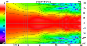
Here is a 150mm x 93mm elliptical waveguide.
6dB beamwidth is 73 ish degrees from 1.5kHz.
There is some amount of narrowing of the 3dB width around 8kHz..
Need to see what can be done about that.. 🤔


6dB beamwidth is 73 ish degrees from 1.5kHz.
There is some amount of narrowing of the 3dB width around 8kHz..
Need to see what can be done about that.. 🤔
Make it round 🙂Need to see what can be done about that.. 🤔
I made it round.. 😀
150mm in diameter, 18mm in depth


It's almost nice now.. still there is something bothering around the 5.5k to 6k region... 🙂
The 2kHz narrowing in the verticals is most probably due to no rounding/chamfer on the edges at top and bottom.. so that can be taken care of partly and then crossover will rip that apart
150mm in diameter, 18mm in depth
It's almost nice now.. still there is something bothering around the 5.5k to 6k region... 🙂
The 2kHz narrowing in the verticals is most probably due to no rounding/chamfer on the edges at top and bottom.. so that can be taken care of partly and then crossover will rip that apart
Sounds great. Since I saw what I have been picturing in my mind I got excited. 🙂. Especially as I have zero skill with ABEC or similar. I was limiting my thinking to large roundovers with cabinet front and back parallel, but know that the shape you drew could be even better. Will be very interested to see what you come up with.At the moment I was just playing around with simulations for understanding how to design a waveguide for the T34A that will allow me to use it with the Purifi PTT6.5M04-NFA-01 paper cone midrange.. But my idea was exactly what you described above:
I think @fluid knows the dome shape of the T34A and may have developed a WG for it (not sure as my list includes those for the T34B)? That seems to be the key to designing WGs for these domes.
Which midrange to match is the next step for me also. Mabat's WG for the T34B is about 60 degrees at XO. I have thought about the Purifi's, but I think the smaller ones may be radiating too widely at the crossover point the T34s allow(?). Though you can raise it, of course, but then I wonder why I didn't get the T25... The sensitivity of the T34s is also so nice, that I wonder about matching it with a less efficient midrange.
Your thread continues to be a great one,
Bill
My biggest comment is that you should attempt push your midrange up higher to 3 kHz and re-evaluate your vertical dispersion. If I remember correctly, you are using LR4? That should make the vertical dispersion better above tweeter axis.
Now make it 16mm deep and make the horizontal sides of baffle shape transition quicker.I made it round.. 😀
150mm in diameter, 18mm in depth
I haveI think @fluid knows the dome shape of the T34A and may have developed a WG for it (not sure as my list includes those for the T34B)? That seems to be the key to designing WGs for these domes.
https://www.diyaudio.com/community/...4a-waveguide-and-purifi-6-5-aluminium.413697/
T34B would be different and not as wide. I have made some simulations with T34B but I haven't pursued it much as it isn't a driver I have or intend to buy.
Thanks @fluid.. 🙂
I reduced the depth to 16mm and put the waveguide in a normal rounded box with 30mm rounding

This is what I get..


6dB beamwidth of 70 degrees 😀
I also have the T34A.. 🙂
I waited for the Purifi tweeter for so long.. but since I couldn't get one, I got the T34A.
Regarding the overall cabinet for this speaker, I want the Purifi 6.5inch + T34A tweeter to sit in a cabinet such that it doesn't look very odd on top of the 52cm wide, 90cm tall dual 15inch bass cabinets.. That is why I was trying to simulate wider cabinets earlier.. Also the tweeter in waveguide would be at the bottom, directly on top of the 15inch midwoofer and the purifi driver further up top like how I placed the SB15CAC + SB26CDC cabinet. This is to get the tweeter at exactly ear height while listening.. I know the vertical radiation pattern of the waveguide will go for a toss with that kind of configuration..
(The SB15CAC + SB26CDC cabinet on top of this bass module looked very odd earlier due to the narrow top module)
I reduced the depth to 16mm and put the waveguide in a normal rounded box with 30mm rounding
This is what I get..
6dB beamwidth of 70 degrees 😀
I also have the T34A.. 🙂
I waited for the Purifi tweeter for so long.. but since I couldn't get one, I got the T34A.
Regarding the overall cabinet for this speaker, I want the Purifi 6.5inch + T34A tweeter to sit in a cabinet such that it doesn't look very odd on top of the 52cm wide, 90cm tall dual 15inch bass cabinets.. That is why I was trying to simulate wider cabinets earlier.. Also the tweeter in waveguide would be at the bottom, directly on top of the 15inch midwoofer and the purifi driver further up top like how I placed the SB15CAC + SB26CDC cabinet. This is to get the tweeter at exactly ear height while listening.. I know the vertical radiation pattern of the waveguide will go for a toss with that kind of configuration..
(The SB15CAC + SB26CDC cabinet on top of this bass module looked very odd earlier due to the narrow top module)
Increasing the roundings to 50mm gets rid of the lower frequency narrow better..


Comparison of SP DI of earlier iterations with 25mm and 30mm rounding vs current 50mm rounding below

Now I better understand why @hifijim did this on his waveguide 🙂

The revel saloon kind of rounding around the waveguide might work closely as well i guess

Comparison of SP DI of earlier iterations with 25mm and 30mm rounding vs current 50mm rounding below
Now I better understand why @hifijim did this on his waveguide 🙂
The revel saloon kind of rounding around the waveguide might work closely as well i guess
Last edited:
I copied the idea from many others who came before me. I was inspired by the experimental work of @Patrick Bateman and a simulation of @mabat. Later on, @tmuikku and I had a long thread where we bounced ideas back and forth, and we came to the conclusion that, if the goal is to reduce the size of the diffraction hump, then the rounded edge should start as close as practical to the edge of the tweeter.
@fluid has reminded me (more than once) that a bit of flat baffle area around a waveguide can provide some directivity at lower frequencies, and this may be useful in some design situations.
@fluid has reminded me (more than once) that a bit of flat baffle area around a waveguide can provide some directivity at lower frequencies, and this may be useful in some design situations.
@vineethkumar01 , a suggestion to simulate, an elliptical curve starting with radius 50mm and end with a smaller radius of say 25mm, effectieve making the width and height of the enclosure a bit smaller.
From my sims i got the impression that the initial radius is dominant. Would be interested in your finding.
From my sims i got the impression that the initial radius is dominant. Would be interested in your finding.
So this is what is possible with both the Purifi 6.5inch and the Bliesma T34 in a shallow waveguide (150mm diameter, 16mm deep).

Waveguide dimensions: 150mm diameter x 16mm deep
Cabinet dimensions: Width x Depth x height = 270mm x 200mm x 394mm
The height dimension can be reduced to 344mm by reducing the rounding at top and bottom to 30mm each instead of 50mm in the current pic. It will definitely have some (probably minor) impact on the vertical directivity.
At least the width dimension & 50mm rounding are needed for proper edge termination of the waveguide & avoiding midrange narrowing with the waveguide I think, although the crossover will probably take care of some of that narrowing part.
Tweeter in waveguide raw response curves (ignore the peaks around 1164Hz. It would be a simulation issue):


Woofer in waveguide raw response curves (ignore the peaks around 1164Hz. It would be a simulation issue):


The full speaker response with a prototype crossover


I think the CTA 2034 curves & horizontal directivity are looking fine and I couldn't probably have asked for more..
What is missing in the modeling is the purifi driver mid break up region and the EQ required to tame it..
But it very manageable with this driver.
Also, because of the weird phase curves for each driver I got from the simulation, I forced the phase to minimum phase option in vituixCAD due to which I don't get any phase matching at crossover for the above curves.

With real driver measurements, I guess it will be more manageable.. 🤔
Ideally, the next logical step for me will be to create a 3D-printed prototype cabinet and take some measurements.. 😀
Waveguide dimensions: 150mm diameter x 16mm deep
Cabinet dimensions: Width x Depth x height = 270mm x 200mm x 394mm
The height dimension can be reduced to 344mm by reducing the rounding at top and bottom to 30mm each instead of 50mm in the current pic. It will definitely have some (probably minor) impact on the vertical directivity.
At least the width dimension & 50mm rounding are needed for proper edge termination of the waveguide & avoiding midrange narrowing with the waveguide I think, although the crossover will probably take care of some of that narrowing part.
Tweeter in waveguide raw response curves (ignore the peaks around 1164Hz. It would be a simulation issue):
Woofer in waveguide raw response curves (ignore the peaks around 1164Hz. It would be a simulation issue):
The full speaker response with a prototype crossover
I think the CTA 2034 curves & horizontal directivity are looking fine and I couldn't probably have asked for more..
What is missing in the modeling is the purifi driver mid break up region and the EQ required to tame it..
But it very manageable with this driver.
Also, because of the weird phase curves for each driver I got from the simulation, I forced the phase to minimum phase option in vituixCAD due to which I don't get any phase matching at crossover for the above curves.
With real driver measurements, I guess it will be more manageable.. 🤔
Ideally, the next logical step for me will be to create a 3D-printed prototype cabinet and take some measurements.. 😀
While thinking about refinements to the design of the purifi-bliesma two way top, I slowly pushed those Satori woofer modules into the living room and tried to put them in not-so-easily-seen places in the room.. 🙂
Then I tried to integrate and create a stereo sub configuration with two subwoofers at the back of the sofa and the 15-inch subs at the bottom of the main speakers. The inspiration is from earlier discussion in this thread and from here:
The bass is pretty awesome now compared to earlier.. 😀
Now I don't have to apply a lot of EQ in cutting down the peaks in the low-end and wondering about what to do with huge dips frequency response in the low end.


That 200Hz dip is still a bothersome thing, at least to the eyes 😉
Need to try to do something about it along the way..
Also need to treat the room more to get rid of some of that flutter echo.

I think technically, it can still be improved a bit more.. And I am still contemplating the practicality and implementation details of the double bass array.
But I am very happy with the bass that I am hearing now..
As an added bonus, I even get free back massages from the sofa due to the 4 x 10inch woofers firing from behind it..
It is a very "moving" experience.. 😀
Then I tried to integrate and create a stereo sub configuration with two subwoofers at the back of the sofa and the 15-inch subs at the bottom of the main speakers. The inspiration is from earlier discussion in this thread and from here:
The bass is pretty awesome now compared to earlier.. 😀
Now I don't have to apply a lot of EQ in cutting down the peaks in the low-end and wondering about what to do with huge dips frequency response in the low end.
That 200Hz dip is still a bothersome thing, at least to the eyes 😉
Need to try to do something about it along the way..
Also need to treat the room more to get rid of some of that flutter echo.
I think technically, it can still be improved a bit more.. And I am still contemplating the practicality and implementation details of the double bass array.
But I am very happy with the bass that I am hearing now..
As an added bonus, I even get free back massages from the sofa due to the 4 x 10inch woofers firing from behind it..
It is a very "moving" experience.. 😀
Last edited:
After a few days/couple of weeks with the "multi-sub" set-up, I feel that this is one of the most noticeable/effective audio tweaks I have made so far.
The bass is so much more satisfying and more even across the listening space.. 🙂
There is a sense of effortlessness in the bass and I can "feel" the bass more in addition to hearing some subtle nuances.
Before I jump into the constant directivity waveguide-based speaker design using the T34A on the waveguide, I decided to first hear what it sounds like without the waveguide. So I made a design for a prototype 3D printed cabinet and am in the process of printing it.. 🙂

The pic above shows the cabinet, with the purifi driver on top and tweeter intended to be placed in the nearby tweeter holder and attached to the cabinet. The holder can be replaced with the tweeter waveguide of the same size when the time comes. The whole cabinet is of the size Width x Depth x Height = 270mm x 200mm x 370mm. The cabinet edges are rounded with about 50+ ish mm radius starting right at the edge of the waveguide/tweeter holder.
The most important reason behind this experiment is that I want to "hear" the difference in sound in my room between the non-waveguided and waveguided versions of the tweeter and then commit to a final build. So far, I had placed 90% of my trust in graphs before jumping into final builds, but now I want to take a step back and give more weight to what I am hearing. 🙂
The bass is so much more satisfying and more even across the listening space.. 🙂
There is a sense of effortlessness in the bass and I can "feel" the bass more in addition to hearing some subtle nuances.
Before I jump into the constant directivity waveguide-based speaker design using the T34A on the waveguide, I decided to first hear what it sounds like without the waveguide. So I made a design for a prototype 3D printed cabinet and am in the process of printing it.. 🙂
The pic above shows the cabinet, with the purifi driver on top and tweeter intended to be placed in the nearby tweeter holder and attached to the cabinet. The holder can be replaced with the tweeter waveguide of the same size when the time comes. The whole cabinet is of the size Width x Depth x Height = 270mm x 200mm x 370mm. The cabinet edges are rounded with about 50+ ish mm radius starting right at the edge of the waveguide/tweeter holder.
The most important reason behind this experiment is that I want to "hear" the difference in sound in my room between the non-waveguided and waveguided versions of the tweeter and then commit to a final build. So far, I had placed 90% of my trust in graphs before jumping into final builds, but now I want to take a step back and give more weight to what I am hearing. 🙂
You tried multisub and DBA? Can you get good cancelation of modes with DBA?
I see that you have big hole at 200 Hz, but longer decay at the same frequency, interesting...can you see some geometrical connection to the room dimensions?
My next project is four active subs...made as a small cubical coffins, to be able to hide them in the room as a furniture...
I see that you have big hole at 200 Hz, but longer decay at the same frequency, interesting...can you see some geometrical connection to the room dimensions?
My next project is four active subs...made as a small cubical coffins, to be able to hide them in the room as a furniture...
- Home
- Loudspeakers
- Multi-Way
- A 3 way design study