look PIC ?
how do you generate 18 V ?
separete PSU or from 140 V VCC / VSS with Resistor and Zener ?
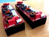
i use seperate 18 0 18 vac trnaformer..as seen at the bottom..
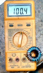
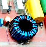
i used 2 core just for test ...it reads 10uh...
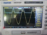
Stewin, also puts an oscillogram at the frequency of 1khz.Thanks.
hi dorel ,it was not my work but the expertise of m.r moore4889
The attachments from moore4889 could not be seen, but if you can picture it at 1khz it would be great.Greetings,
hi sir ... want to ask, if you make 3 steper ic IR2117, what size zener diode input for HV and LV?
Last edited:
The attachments from moore4889 could not be seen, but if you can picture it at 1khz it would be great.Greetings,
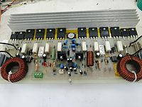
thanks for the simulations and photos but please post bigger pictures
thanking you in advance steven.
Hi moore
Great, but do you know switching frequency from TD Rails `?
apex talk about something 50 khz,
can you check whats switching frequency from your TD Rail ?
regards

greetings sir apexaudio..i have already build your B500 sir..i would like to ask what is the power of this H900 TEF sir?thanks and regards
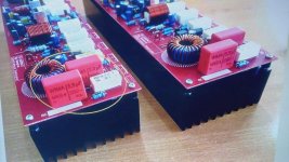
Nice work, dont forget wire jumper.
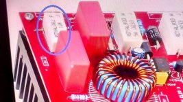
what is the red colred wire here dude
Yes, and 2x18V 500mA, but not bound.

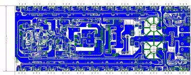
do you have pcb layout of the attached file sir
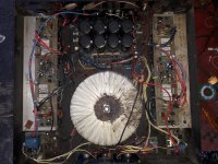
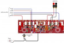
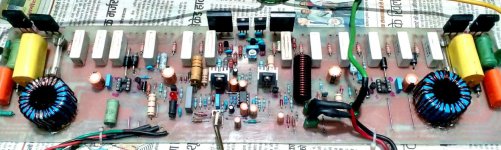
I have completed TD 1800 as per schematic , but having problems, which along with marked photos I am posting. please Mr. Miles Guide
Positive side high voltage dropping too much, Amplifier section is similar to your h-900 but I can see changes, which I have marked.Also am confused as in some photos, positive side 5 watts resistor is of 10 k ohm , whilst in schematic it is 2.2 k ohm, Also capacitors in schematic are 3.3 uf and 10 uf. whilst in photo all 4 capacitors are 3.3uf. which also I have marked, I was able to switch on audio with 18-0-18 volt d.c., but biasing milli volt is too high 570 milli volt base to emmiter output transistor. please guide.
Positive side high voltage dropping too much, Amplifier section is similar to your h-900 but I can see changes, which I have marked.Also am confused as in some photos, positive side 5 watts resistor is of 10 k ohm , whilst in schematic it is 2.2 k ohm, Also capacitors in schematic are 3.3 uf and 10 uf. whilst in photo all 4 capacitors are 3.3uf. which also I have marked, I was able to switch on audio with 18-0-18 volt d.c., but biasing milli volt is too high 570 milli volt base to emmiter output transistor. please guide.
Attachments
-
 81226843_2631788973584502_651682057906290688_n.jpg104.6 KB · Views: 361
 -
 68359007_1482533771889218_437424388824891392_n - Copy.jpg351.7 KB · Views: 340
 -
 81227204_2812334778810891_7910266119171080192_n.jpg141.3 KB · Views: 366
 -
 71495976_1521202494689012_436232844637896704_o.jpg201 KB · Views: 363
 -
 80434670_498033634157449_5311001578633691136_n.jpg143.3 KB · Views: 502
 -
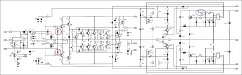
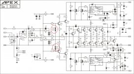 APEX H900 SCH V1 - Copy.jpg757.3 KB · Views: 853
 -
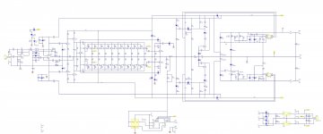
 CORRECTED TD CLASS - Copy (2).jpg515.4 KB · Views: 932
 -
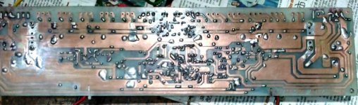 81471133_581016272700216_7711339146874191872_n.jpg77.4 KB · Views: 845
 -
 81098086_585421975609346_877364670707531776_n.jpg104.8 KB · Views: 871
please give me black layout of the board sir, thanks a lot
I have completed TD 1800 as per schematic , but having problems, which along with marked photos I am posting. please Mr. Miles Guide
Positive side high voltage dropping too much, Amplifier section is similar to your h-900 but I can see changes, which I have marked.Also am confused as in some photos, positive side 5 watts resistor is of 10 k ohm , whilst in schematic it is 2.2 k ohm, Also capacitors in schematic are 3.3 uf and 10 uf. whilst in photo all 4 capacitors are 3.3uf. which also I have marked, I was able to switch on audio with 18-0-18 volt d.c., but biasing milli volt is too high 570 milli volt base to emmiter output transistor. please guide.
which coil T-157 ?
how many turns ?
do you have
- Home
- Amplifiers
- Solid State
- 900W H-class PA Amp with Limiter