hello sir
i want to add a mute led in my amp ...??
pls help me
thank u ...
What will be funktion of mute led?
Mr.Mile
my H900 in the process..
I want to ask, whether IR2117 can be replaced with IR2118
thank's
my H900 in the process..
I want to ask, whether IR2117 can be replaced with IR2118
thank's
i need daily led when amp plug in power led is on and .after rely daily time when amp start led is turn off.
thank u sir...
thank u sir...
i need daily led when amp plug in power led is on and .after rely daily time when amp start led is turn off.
thank u sir...
That funktion have PROTECT LED on protection circuit pcb.
Mr.Mile
my H900 in the process..
I want to ask, whether IR2117 can be replaced with IR2118
thank's
No IR2118 have inverted input.
No IR2118 have inverted input.
terimakasih mr.mile hehehe..... i now understand, your PA so nice..... i'll waiting for your another idea, thank's 🙂
hi apex
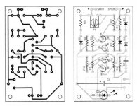
iam planning to make h900 please check the pcb layout .i have widen the tracks as pcbs
availability is of very poor quality.and also can 2 parallel 15 volts zener be used instead of 1 zy15.polarity of bf422/423 is changed will correct it.thanks in advance.
http://img526.imageshack.us/img526/8438/39092467.gif
ravs
be a vegeterian.....
Attachments
Last edited:
versions
hello have you test this lay out so far?
new PCB vesiune designed for active subwofer
I'll make a test PCB next week, if we think changes should be made I expect corrections
hello have you test this lay out so far?
hi apex
iam planning to make h900 please check the pcb layout .i have widen the tracks as pcbs
availability is of very poor quality.and also can 2 parallel 15 volts zener be used instead of 1 zy15.polarity of bf422/423 is changed will correct it.thanks in advance.
http://img526.imageshack.us/img526/8438/39092467.gif
ravs
be a vegeterian.....
I suggest to use +/-MV and 1k/2W instead 6k8/2W to get +/-15V for ICs,
Nice pcb, do you use coolets pcb as start point?
Regards
I suggest to use +/-MV and 1k/2W instead 6k8/2W to get +/-15V for ICs,
Nice pcb, do you use coolets pcb as start point?
Regards
hi apex,
will do so as you suggest did you find any other error.and also can two 1 watt
zener be used instead of 1 2watter.yes i used some part as a reference from his
pcb.ill start etching the pcb as soon as you verify it.
thanks
ravs
be a vegeterian......
to ravslanka (u have done a great job)
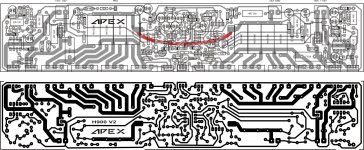
i just love ur layout , i am gonna use ur layout, i have attached the picture of ur pcb with a few red circles whr i think the traces should be a bit thin cause producing high resolution pcbs is nt always possible and there can be shorts , so if possible reduce the track size at the indicated positions ............. and can u add few more o/p transistors if possible just to be on the safe side.
regards
sekhar
Attachments
hi apex,
will do so as you suggest did you find any other error.and also can two 1 watt
zener be used instead of 1 2watter.yes i used some part as a reference from his
pcb.ill start etching the pcb as soon as you verify it.
thanks
ravs
be a vegeterian......
I will verify final pcb, what is pcb size.
You can use one 1W zener if you use +/-MV.
Regards
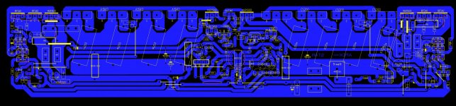
pcb copper side
Hello can you pls share your pcb on mirror/ copper side I'd like to try your designfor this monster amp you need a 1mm solid wire layed and soldered to the pcb track as shown in picture... light blue color traces.😉
How much power do you want ?
With 2 step class-h with 1943/5200 pairs you cant increase your rails beyond 70VDC per step. Around 3.5kW could be manageable with 14-16 pairs at output for continuous duty cycle operation into 2 ohms.😉
h900v2 + another output pair
power is up to 3.5kw
Attachments
![TOP%20%2B%20BOTTOM%20%20LAYER%20H900[3].PNG](/community/data/attachments/195/195944-77d316ae9190f6f40406d74569ca368c.jpg?hash=d9MWrpGQ9v)
miles what mosfet can replace irf540 that comes in plastic package like 2sc4793........??????????????????
regards
sekhar
regards
sekhar
- Home
- Amplifiers
- Solid State
- 900W H-class PA Amp with Limiter