Yes, step driver from Zeck PT-9 upgrade with extra higher voltage fets.Step Driver schematic from Zeck Audio power amplifier PT series?
Last edited:
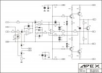
will add Class H Step Driver in Quasis NMOS Amplifier schematic
after finished schematic will upload here, lets check for faults
hope it will work
after finished schematic will upload here, lets check for faults
hope it will work
power amp
hi qsa
greetings how is power amp n mos sounding and stability
trying to make it but gerber files to complicated any new modifications
please let us know will keep trying as i have all components
thanking you
andrew lebon
hi qsa
greetings how is power amp n mos sounding and stability
trying to make it but gerber files to complicated any new modifications
please let us know will keep trying as i have all components
thanking you
andrew lebon
I have no expirience with amplifiers in H or G class which using mosfet in output stage. With BJT have no problem.will add Class H Step Driver in Quasis NMOS Amplifier schematic
after finished schematic will upload here, lets check for faults
hope it will work
Do anyone want to DIY something like that?
Hello apexaudio. I am concidering to DIY the amplifier after i will finish a 2KW SMPS project with my girlfriend (helping her to learn electronics for school). Thank you for the the PCB design.
![P1553[01]_17-03-10.jpg](/community/data/attachments/149/149554-fcadf4dedaaeda5d286cbf1a5952fdfa.jpg?hash=_K303tqu2l)
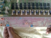
Nice work, dont forget wire jumper.hi apex audio
greetings pcb ready inserting components some pics
thanking you
andrew lebon
Attachments
I am interested about this 2kW SMPS, can it give 4x55V DC?Hello apexaudio. I am concidering to DIY the amplifier after i will finish a 2KW SMPS project with my girlfriend (helping her to learn electronics for school). Thank you for the the PCB design.
I am interested about this 2kW SMPS, can it give 4x55V DC?
the original schematic I will use actually delivers 2 x 60V dc. but it can be modified. i will keep you informed about the way things are going.
regards,
Then can be used two in series circuit 🙂the original schematic I will use actually delivers 2 x 60V dc. but it can be modified. i will keep you informed about the way things are going.
regards,
Then can be used two in series circuit 🙂
hello apex,
I will redesign the secondary part and make it +110v, +55v, GND, -55v, -110v
is that what you need?
regards,
Yes, and 2x18V 500mA, but not bound.hello apex,
I will redesign the secondary part and make it +110v, +55v, GND, -55v, -110v
is that what you need?
regards,
Yes, and 2x18V 500mA, but not bound.
hello apex,
I will try to design the PCB and publish the schematic this weekend. If it's all good I will start work on it next week. All I need is to get proper litz whire, aditional low ESR caps, and another ferrite core.
regards,
If you need some help, I have SMPS electronic circuit...hello apex,
I will try to design the PCB and publish the schematic this weekend. If it's all good I will start work on it next week. All I need is to get proper litz whire, aditional low ESR caps, and another ferrite core.
regards,
Regards
Hello apexaudio
Do you have some SMPS schematics that can be use with most class A/B amps ?
Thank
Bye
Gaetan
Do you have some SMPS schematics that can be use with most class A/B amps ?
Thank
Bye
Gaetan
Yes but I use wired ferite core of Behringer, and I dont know kind and number of turns.Hello apexaudio
Do you have some SMPS schematics that can be use with most class A/B amps ?
Thank
Bye
Gaetan

If you need some help, I have SMPS electronic circuit...
Regards
hello apex,
maby it would be some help. i have some experience in building smps. send post the schematic or send it by mail (savu_silviu@hotmail.com).
regards,
Comutation diode SFA1603 in negative side have wrong direction, be more careful.hi apexaudio
greetings work in progress
thanking you
andrew lebon
Regards
- Home
- Amplifiers
- Solid State
- 900W H-class PA Amp with Limiter