IOTA-CD vs DOGC-MK3
So..any new builders of IOTA-CD out there? Waiting for your reviews or comparison with DOGC. I was given old amplifier which could be used for IOTA-CD.
So..any new builders of IOTA-CD out there? Waiting for your reviews or comparison with DOGC. I was given old amplifier which could be used for IOTA-CD.
There is little to be gained with this type of hybrid.
I designed my own in a similar style and the sound still sounded like SS.
If you really want the warm valve sound then you need complete valve amplifier with OT.
I designed my own in a similar style and the sound still sounded like SS.
If you really want the warm valve sound then you need complete valve amplifier with OT.
There is little to be gained with this type of hybrid.
I designed my own in a similar style and the sound still sounded like SS.
If you really want the warm valve sound then you need complete valve amplifier with OT.
I am not looking to emulate all valve amplifiers. I am just curious if tube in input stage brings something better than mosfet input - more natural sound, bigger soundstage etc.?
I am not looking to emulate all valve amplifiers. I am just curious if tube in input stage brings something better than mosfet input - more natural sound, bigger soundstage etc.?
It doesn't unless you do something unusual with the bias conditions.
IOTA-CD finally built
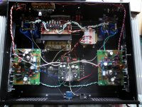
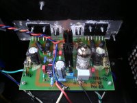
Today, I have finished my IOTA-CD build. I have used the same components and rail voltages as in my DOGC-H build.
For input tube I am using Tesla PCC88. Amplifier works very well, no hum, buzz etc.
Now for the sound difference betwen DOGC-H (mosfet input) and IOTA-CD (tube input).
There is definately a difference, not night and day, but it is there.
IOTA-CD is warmer, soundstage seems to be wider and deeper, smoother.
DOGC-H is tighter, punchier, colder in the mids, maybe little more detailed.
Differences are really quite small. Both amplifiers sounds superb to me. It is just matter of taste / flavor.
If anyone interested I can send him mine PCB designs for IOTA-CD, IOTA-CD PSU and DOGC-H.
Thanks Bora Jagodic for these great designs!
Can you explain what software used ?Hi,
here are mine latest PCBs for IOTA-CD amplifier. I am now gathering parts for the build. For input tubes I have some Tesla PCC88. Hopefully I will finish amplifier in two months or so.
I can't see the zip content.
Sorry i see files now.Can you explain what software used ?
I can't see the zip content.
Hi Vostro, see my hybrid front-end project here - Low TIM, low distortion hybrid front-end - maybe this is something you are looking for. It is fully prototyped, tested and documented.
It may be successfully used with a number of power sections, one of then is shown there in my thread, the other good option is Ostripper's Slewmonster.
More detailed measurements are available here - Measurements - Hybrid with tube
Listening impressions will be available over the weekend, though - no doubts - they don't promise to be bad 😉
Terry (still4given) will have some spare PCBs for this design.
Cheers,
Valery
Where can I buy this PCB hybrids. Give the address where you order it!?
thanks!
Hi all!I have made some changes on PCBs, just minor tweaks.
PCB (top and botton layer) please in pdf format.
thanks you!
Last edited:
Hi all!
PCB (top and botton layer) please in pdf format.
thanks you!
PCB is in Eagle format. You can download free version of it.
Hi ppl 🙂
I have a problem with this amplifier, i cant turn it on.
I have large dc out -42V, all negative supply, and the MJE350 drawn about 71mA of current, and it smokes 620ohm resistor on HV supply, resistors are like on the schematic.
And what works:
Current on E88cc can be adjusted from 7,6mA-9,2mA, on IRF9530/530 i have 193mA, 3,3ohm resistor. I desoldered the power transistors, they look like good, i can mesure them, so are MJE, IRF. And dont know what to think about it. I soldered both channels, same symptom.
Opamp voltage +-12V tl071.
Dont know what i can say more ....
Attachments

Something is bad around differential amplifier.
I have built this amplfiier too. In comparison to DOGC-MK3 or DOGC-H which uses MOSFET differential input, the sound difference is very small. So if you wont find the mistake you can built mosfet one, sounds equally good and is easier to built.
I have built this amplfiier too. In comparison to DOGC-MK3 or DOGC-H which uses MOSFET differential input, the sound difference is very small. So if you wont find the mistake you can built mosfet one, sounds equally good and is easier to built.
Bad tube maybe. Check grid, cathode, and anode voltage. Anode voltage should be around 75-85V, and grid voltage about 2V lower than cathode voltage. Anode currents should be equal too, check BC640.
looks like you should get +42 v until tube is heated.
it's a poor design.
high side and low side should both be off if tube is not heated
Your MJE 350 may be bad as it should be off until tube is heated
collector and emitter current should be almost exactly the same
it's a poor design.
high side and low side should both be off if tube is not heated
Your MJE 350 may be bad as it should be off until tube is heated
collector and emitter current should be almost exactly the same
Last edited:
Just another question: What's the purpose of these lowish values of both the NFB resistors? Hey, it's a tube amplifier, regarding the LTP, and these values can easily be 10 to 20 times as high!
Best regards!
Best regards!
Just another question: What's the purpose of these lowish values of both the NFB resistors? Hey, it's a tube amplifier, regarding the LTP, and these values can easily be 10 to 20 times as high!
Best regards!
It is part of the bridge network, which is needed by current dumping technique to work properly.
- Status
- Not open for further replies.
- Home
- Amplifiers
- Solid State
- 80W Hybrid Audio Amplifier!