Is it wise to use 1 Mosfet/channel or can 1 be shared betwen left/right?
It can be shared between dozen of channels.
What % do I get if I use Zener string and a Mosfet?
More than plenty. However, Miles may disagree, but he prefers exotic tube overkills. ;-)
Last edited:
Nothing is wrong with VR tubes, if they are used as reference voltage regulators.
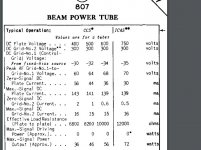
It is a matter of their current capability. If g2 current is small, just naked VR may be sufficient. This is exactly the case of 807 run at extreme plate voltages. Maximum g2 current for a PP pair at 750 V plate and 120 W output in AB2 is 20 mA, well within the limits of octal VRs. In AB1, a string of VRs may have enough current for four 807 screens.
In AB2, there is no kind of clipping that you are talking about. It is cathode stripping, if driver has enough capability. And, I don't play guitar; I listen to recorded music.
Last edited:
Try it... It has nothing to do with cathodes. Even in A1 the tube hits saturation on peaks of sounds, due to crest factor, that extinguishes the tube. The voltage then increases sharply, up to the ignition point, then drops down. Try it; it is awful sound!
Attachments
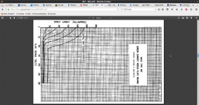
Quick calculation. In tabulated AB2 operation at 750 V, control grids swing 13 V positive at the peak output power of 120 W. Static current draw at Ug1=+13 V, Ug2=250V, and Ua=750V is about 350 mA, and corresponding Rp is 2.1 K. With single tube plate load of 3.6 K (half the optimal P-P load), plate voltage is (750x2.1)🙁2.1+3.6)=276 V. Now, looking at the graph in your post, at Ug1=+13 V, Ua=276 V, and Ug2=250 V, screen current is ~10 mA. So, at maximum signal swing, the tube is very far away from collapse.
What limits output power is not plate voltage swinging too low, but 120 mA steady current capability of the tube (240 mA at maximum power for the pair).
Allowable cathode current limiting power output in AB2 can be seen in data sheets of other power pentodes. For example, the similar 1624 has Ikmax of 90 mA, so power output is limited by 180 mA current draw of the PP pair.
Are you sure your load line is straight? Are you listening resistors, instead of speakers?
Try it...
Try it...
Anatoly - I am reading over again through your post, trying to reconcile what you are saying with the posted graph. If you are talking about tube collapse as exhaustion of its current capability, then there is no daylight between our points. But if you argue that momentary screen current may become excessive at signal peaks, my previous post shows that cathode current capability is exhausted way before screen current becomes excessive.
I am talking about screen grid current peak that extinguishes the VR tube that needs higher voltage to ignite than to glow. You can't have more than 30 - 40 mA current through a VR tube. That means, as soon as screen grid current exceeds this value you are getting nasty distortions. That's why a source (or cathode follower) is needed to power screen grids.
https://frank.pocnet.net/sheets/137/0/0B3.pdf
Of course I am not going to push on you. If you disagree, it is your matter. ;-)
https://frank.pocnet.net/sheets/137/0/0B3.pdf
Of course I am not going to push on you. If you disagree, it is your matter. ;-)
Are you sure your load line is straight? Are you listening resistors, instead of speakers?
Try it...
A very interesting point. Pentode output stage in its pure and simple form requires load whose impedance changes little with frequency. A conventional box speaker is not such load, so pentode purity is usually adulterated with various feedback schemes to accommodate such speakers. This negates the advantages of pentode output stage as current source, turning it into voltage source. And, of course, at boxed speaker's main resonace, Z may become 10 times the nominal or more, wreaking havoc in screens.
But if the mountain doesn't go to Muhammad, then Muhammad goes to the mountain. That is, pentodes require special speakers to reveal their advantages. For examples of such speakers one may look back to 1930s-40s, when 6L6 and 6V6 pentode amplifiers did not use any kind of feedback. Speakers used with these amplifiers did not have resonant box enclosures, and, having low Qms, did not depend on damping by amplifier. They had only moderate increase in Z at main resonance.
My favorite speakers for a pentode amp are antique field coil 12" Magnavoxes in open baffles. They have pretty uniform impedance up to 8 kHz. They are good as they are, but I believe can be further improved with aluminum former and voice coil ( a project for some remote future).
For the top end it is Bohlender-Graebener NEO-3, which has purely resistive impedance all over its range.
So, I am indeed listening to speakers that look like resistors to amplifier's output.
Last edited:
i understand Anatoly re: regulators instead of as reference.
a resistor follows ohm's law, a mosfet source follower somehow do not
and therein lies the difference...
a mosfet or even tube followers will have lower impedance than any resistor can....
in that application....
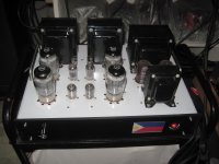
this is a 6550 pp amp that i made using mosfet regulated G2 supply....the owner was very happy....
a resistor follows ohm's law, a mosfet source follower somehow do not
and therein lies the difference...
a mosfet or even tube followers will have lower impedance than any resistor can....
in that application....
this is a 6550 pp amp that i made using mosfet regulated G2 supply....the owner was very happy....
Attachments
I am talking about screen grid current peak that extinguishes the VR tube that needs higher voltage to ignite than to glow. You can't have more than 30 - 40 mA current through a VR tube. That means, as soon as screen grid current exceeds this value you are getting nasty distortions. That's why a source (or cathode follower) is needed to power screen grids.
https://frank.pocnet.net/sheets/137/0/0B3.pdf
Of course I am not going to push on you. If you disagree, it is your matter. ;-)
Point well taken. But with 500 V difference between screen and plate, screen current is very unlikely to exceed 30 mA under normal listening levels. It is not a stadium PA or guitar amp to use full blast at 120 W.
Let me reveal one more secret: in my amps with 800V B+ and 270V G2 I use G2 current to control anti-clipping input optical attenuator. ;-)
Schematic?
Joking apart, cathode follower after VR tube will solve current problem only to the extent of its own current limitation. That is, for 100 mA current capability, the follower has to run at 100 mA idle current or more. 30 mA of VR tube is plenty of current.
Joking apart, cathode follower after VR tube will solve current problem only to the extent of its own current limitation. That is, for 100 mA current capability, the follower has to run at 100 mA idle current or more. 30 mA of VR tube is plenty of current.
Joking apart, cathode follower after VR tube will solve current problem only to the extent of its own current limitation.
You still did not get it. Explaining the last time.
The G2 current is supplied by source, or cathode, follower. VR tube always works on the same current, always glows. No abrupt changes of a voltage on it due to the fact that ignition and glowing voltage are different.
I get it. One thing I don't understand is what's the big deal about VR tube extinguishing. Once it stops conducting, the circuits simply reverts to screen supply via voltage dropping resistor until VR ignites again.
It not simply reverts. G2 also controls anode current, so chainsaw modulation of it's voltage caused by ignition voltage of VR tube higher than glowing one modulates anode current causing peaks sounding nasty.
Did you get it finally?
I am out, sorry... PLEASE CLICK HERE TO OPEN THE DATASHEET! - during 2 pages you are arguing about irrelevant topics instead of trying to understand the mistake of powering G2 from a parametric stabilizer with VR tube.
Did you get it finally?
I am out, sorry... PLEASE CLICK HERE TO OPEN THE DATASHEET! - during 2 pages you are arguing about irrelevant topics instead of trying to understand the mistake of powering G2 from a parametric stabilizer with VR tube.
Schematic?
for 100 mA current capability, the follower has to run at 100 mA idle current or more. 30 mA of VR tube is plenty of current.
the series device, mosfet follower or cathode follower will pass the zero signal G2 current,this is its idle current. also passes the maximum signal G2 currents...
a look at the data sheet makes this obvious....
Attachments
- Home
- Amplifiers
- Tubes / Valves
- 807 Sound Quality?