You can. I tried it, but feeding them via an RC filter from B+ sounded better. Zeners sounded grainy and thin, midrange was dead and top end was noisy. Tried quieting them with caps but it did not help much.Ok,do i use zeners to stabilizie Vg2 then?
Implementing the RC filter: From 350V to 250V we need to drop 100V, at 2.5mA, that is: you need a 40K resistor (I recommend an 1W or 2W KOA Speer carbon film) and a smallish value, high quality plastic cap to ground (10-20uF or so, value not critical - quality matters more). Separate RC filters for each screen.
Such high resistance in G2 power would cause dependence of distortions on the sound envelope. I.e. dynamic distortions. It may be good for a guitar amp to add some punch and sag, but not for the amp that should bring you to the environment where the sound was recorded.
It is not what I meant.
If you open datasheet for some 807 (or 6L6) clones, like some from Britain tubes I saw with very thorough measurements, you can see that for optimal power/distortions the tube should dissipate 50W or more on anode, that is impossible by design, so forget about optimum, and think of acceptable distortions. I've found 400V on anode / 250V on screen grid in class A is the way to use the tube in push-pull, according to my very critical demand to sound quality.
What's the point in building "just one more tube amp", if it is not of excellent quality?
to quote Tim de Paravicini, "not the tube per se, but the topology and the output transformer that matters..."
. 🙂 Why you should assume that the topic srtarter is the one and hijack his thread? I don't know.
Valid question, I just didn't want this to be about tube vs. so or SE vs. PP. but I still design for low distortion...though I prefer no distortion, 2nd order being higher than 3rd order is more acceptable to me. I do believe keeping all distortion low as possible is best.
I do prefer SE and I do think the 1625 (807) sounds good in an SE application that uses parameters different than what is in the datasheet. I have listened to 6BG6's (octal 807 variant) using low B+ and did not like the results. A higher B+ definitely made a significant improvement.
How much higher,are we talking triode or tetrode?A higher B+ definitely made a significant improvement.
200VDC
I heard it at 270VDC, 320VDC and 516VDC B+... all in triode mode. The high the B+ had better sound in triode IMHO
516VDC
I heard it at 270VDC, 320VDC and 516VDC B+... all in triode mode. The high the B+ had better sound in triode IMHO
516VDC
What OPT where used?The high the B+ had better sound in triode IMHO
This is getting harder day by day to know how to build.... 🙂
What is the plate to cathode voltage in this set up at the stated B+ of 516 V?
~452VDC
What OPT where used?
This is getting harder day by day to know how to build.... 🙂
The lower voltages I used both 11.6K and 14K. The 516VDC I used 14K...I also used 2.6K, 4.6K on the lower voltages.
The 14K are vintage OPT's...they are small.
Now here's the crazy part... the 10.6K is actually a 220vac pri - 12.6vac ct 2A filament transformer...basically 25Watt transformer. I run off of 120V over in the states.
I used it 1 part of the sec. to the center tap... which translates to 120vac to 3.15vac. I used it just to try out... but it has worked so well that I continue to use them. The DC resistance on the primary is less than 200 ohms... and this helps the high frequency response. I really don't understand how these transformers work so well.
Also, I think these are sealed with older waxy type of glue/ epoxy. Very easy to take apart...so I think they are made not as well, and results in less efficiency, and less saturation.
I also used a 5K OPT at 4 ohms... I use it with 8 ohms giving ~10K impedance. The sound is not that different from the above power trsfmr...definitely not enough for me to tell in a blind test.
As far as what to build, take a piece of wood, terminal strips and screw everything down to it. You can then plug and play, change resistor and cap values, along with going from going from pentode to triode. Use stand offs for bolting down the sockets.
For safety, you can cover the circuitry with clear Acrylic using stand-offs.
Once you find what you like...put it into a chassis.
Also, use breakers if you can... 2.5- 4A between the wall input and the transformer primary(s). You need this or fuses for safety devices. The first thing I find before starting is a breaker.
Safety... electrocution is not a viable option...
Thank you janos,
I try...
I was hoping I would get at least one response 🙂 and a delightful response it is.
I wish there was a way to earmark your post. You pinned down so many critical issues about loading with clarity, that I would recommend it as required reading material for tube amplifier designers - both beginner and advanced.
While most people (including me) start/started with taking operating points from datasheets, knowing how loading impacts on power supply demand, and other parameters, allows much greater range of experimentation with better results. The advantages of higher loading are vastly under-utilized.
Cheers,
Janos
Such high resistance in G2 power would cause dependence of distortions on the sound envelope. I.e. dynamic distortions. It may be good for a guitar amp to add some punch and sag, but not for the amp that should bring you to the environment where the sound was recorded.
Thanks for the tip, Wavebourn!
Indeed, having much lower resistance is a much better choice. Actually, a much better (but more complex + much more chassis space) way to get the 250V from the 350V would be to use VR tubes. This is how I would build it now:
0D3 and 0C3 in series gives about 260V. (The exact volts is not an issue, much more important is its stability). Run them at about 30mA (VR+screens). Dropping about 90V at 30mA we need a 3K resistor to feed the VR tubes from the 350V source. This resistor will run very hot, use at least a 15W rated resistor there. Use one pair of tubes to feed both screens. VR tubes have a slight hiss, that can be quieted down with a little capacitance (5-10nF) afterwards. For any bigger capacitance, de-Q it first, and then you can add any capacitance after the VR tube. But there's no point of adding anything bigger than 1uF or so, as the VR impedance is much lower than cap impedance - you'll only make it worse. The purpose of the cap is to settle down the VR noise.
somehow, i like the sound of G2 regulated pentodes better than ultralinear mode....but this is just me.....😉
somehow, i like the sound of G2 regulated pentodes better than ultralinear mode....but this is just me.....😉
Just me too. ;-)
Also, when I regulate screen grid supply, I like to regulate also G1 supply, if it is not a self-bias stage. Also, I like to power preamp tube filaments by regulated DC. Also, I like regulated B+ for preamp tubes. ;-)
And no way I am dropping constant voltage using VR tubes nor zeners, making variations of G2 supply even wider than caused them variations of B+! 🙂
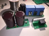
I just use one Zener string, and take reference voltages from it, to gates of source followers using small cheap MOSFETs.
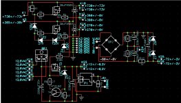
Like here:
Attachments
Last edited:
Is 10% regulation enough? In tube data sheets, for low distortion they recommend not worse than 3% and 5% for g1 and g2 voltages, respectively.
What's wrong with VR tubes? When done right, they provide better than 2% regulation. I wouldn't obtain g2 supply by dropping B+, especially if that is 750-800 V. It is much better to have a completely independent g2 supply from a separate transformer.
I also like stacks of Li ion cells for g1 fixed bias. At 4 V, these cells have very low self discharge and keep steady voltage for years. Rock solid and completely unaffected by line voltage or amp current draw.
somehow, i like the sound of G2 regulated pentodes better than ultralinear mode....but this is just me.....😉
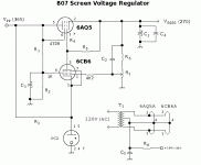
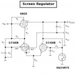
Me three. I include active screen regulation. This wasn't used much back in "the day", and even VR tube regulation was pretty rare, but it's worth it for sonic performance. These are series pass regulators. The design that uses an unbalanced differential error amp is somewhat better in that the noise from the voltage reference can be filtered, besides it allows you to use those 6X8s. Both are quite effective in stabilizing the screen voltage.
You could also solid state these regulators, but I didn't do that since I didn't have any high voltage transistors, and I'd already done that loads of times before, so this was different. Trioded 6AQ5s work nicely as series pass devices.
Attachments
I just use one Zener string, and take reference voltages from it, to gates of source followers using small cheap MOSFETs.
In tube data sheets, for low distortion they recommend not worse than 3% and 5% for g1 and g2 voltages, respectively.
What % do I get if I use Zener string and a Mosfet?
Is it wise to use 1 Mosfet/channel or can 1 be shared betwen left/right?I just use one Zener string, and take reference voltages from it, to gates of source followers using small cheap MOSFETs.
- Home
- Amplifiers
- Tubes / Valves
- 807 Sound Quality?