Internal maybe, but more problem to external 🙁Internal routing probably
Internal maybe, but more problem to external 🙁
I don't really see a problem, what are you worried about?
Aside from putting the digital supply LDOs near the dac chip, you may recall Chris' expressed preference for putting MCLK generation on the dac board. Running MCLK though connectors and a backplane makes it much harder to minimize clock jitter and certain adverse effects on sound quality.
Also, might be useful to figure out how to prevent destruction of the dac chip by someone hot-plugging/unplugging the module. Zener diodes might work and are suggested by AKM for protection against improper power sequencing of I/V opamp rails, but that approach should probably be tested first on the eval board to determine possible effects on sound quality.
Also, might be useful to figure out how to prevent destruction of the dac chip by someone hot-plugging/unplugging the module. Zener diodes might work and are suggested by AKM for protection against improper power sequencing of I/V opamp rails, but that approach should probably be tested first on the eval board to determine possible effects on sound quality.
Last edited:
LDOE would normally be hardwired.
PSN normally hardwired too.
Also, CAD0 and CAD1 are more typically hardwired to set a predetermined address.
Mark,
Thank you, this is super helpful.
So, that means that we have only 5 pins to deal with. It's kinda hard to justify an 8-bit shift register just for that, because it will take 2 or 3 pins at a minimum to get properly driven... So, we might want to dedicate 5 pins on the MCU for these. And it would make debugging on some kind of development board a lot easier, by letting us use some DIP switches.
Let's keep things simple then....
Aside from putting the digital supply LDOs near the dac chip, you may recall Chris' expressed preference for putting MCLK generation on the dac board. Running MCLK though connectors and a backplane makes it much harder to minimize clock jitter and certain adverse effects on sound quality.
Also, might be useful to figure out how to prevent destruction of the dac chip by someone hot-plugging/unplugging the module. Zener diodes might work and are suggested by AKM for protection against improper power sequencing of I/V opamp rails, but that approach should probably be tested first on the eval board to determine possible effects on sound quality.
Yes, we will put the clock on the board. Is there some reference circuit that I could look at for that part?
I'm still not convinced about the need for protection that you're talking about. The DAC board will be mounted onto the PSU board in such a way that hot removal is impossible when the brick's frame and cover are installed. And during development, there are many other things that one can make to break the whole thing, so I would not make the design any more complex than it already is just trying to prevent this thing from happening. It's a bit like with a programming language: there is no way to prevent someone from programming an infinite loop or generating a null pointed exception. And any attempt at making the porgramming language fool-proof ends up creating a sub-optimal language (Java is a great example of that pitfall).
Any thoughts on how the backplane that interconnects modules will be architected? I am wondering if dac modules will be restricted to particular module slots due to special interconnection requirements for AK4499 dac between power, USB and other modules. Doesn't seem possible that any of them could be plugged into any module slot in the backplane and still have things connect up right.
I don't really see a problem, what are you worried about?
Mclk pin is at the north.
I2S/TDM buses - are at the south, and should include also Mclk.
But there are analogue circuits at the east and west - it in not a good idea to route Mclk close to analogue. So there is only one path - through the center of the chip, which is hardly to do with 2 layer PCB.
Any thoughts on how the backplane that interconnects modules will be architected? I am wondering if dac modules will be restricted to particular module slots due to special interconnection requirements for AK4499 dac between power, USB and other modules. Doesn't seem possible that any of them could be plugged into any module slot in the backplane and still have things connect up right.
Based on my current design, it should be possible to connect a DAC brick through any pair of OTO™ sockets on the backplane (what I call the "plate"). But some sockets might not be populated with the necessary power conversion components required to drive the DAC brick when used for simpler bricks like a rotary encoder.
In other words, the design is totally generic.
Mclk pin is at the north.
I2S/TDM buses - are at the south, and should include also Mclk.
But there are analogue circuits at the east and west - it in not a good idea to route Mclk close to analogue. So there is only one path - through the center of the chip, which is hardly to do with 2 layer PCB.
We will probably have 10 or 12 layers for the DAC board. 6 at a very minimum.
Based on my current design, it should be possible to connect a DAC brick through any pair of OTO™ sockets on the backplane (what I call the "plate"). But some sockets might not be populated with the necessary power conversion components required to drive the DAC brick when used for simpler bricks like a rotary encoder.
In other words, the design is totally generic.
Offhand, I can think of two ways to do that, either with a bus structure (shared resource), or maybe a network structure that routes traffic from a source module to a destination module (potentially more flexible but more complex and expensive).
Some other way?
Offhand, I can think of two ways to do that, either with a bus structure (shared resource), or maybe a network structure that routes traffic from a source module to a destination module (potentially more flexible but more complex and expensive).
Some other way?
Oh no, it's much simpler than that. The plate is a 3 × 3 backplane, while the DAC brick is 2 × 1 (plus 1 × 1 bargraph brick) or 3 × 1, therefore you cannot put more than 3 DAC bricks on a plate. And each plate is subdivided into three columns or 3 sockets, with one STM32H743 MCU per column. Therefore, you have one MCU per brick.
I reckon that it must be positively impossible to follow all this without proper schematics and CAD models. I wish I could produce them faster, but I really can't (I have a full-time job in parallel to all this). They'll come in due time though...
Where does the USB board go, and where to clean power supplies dedicated to dac functions come from? The plate/backplane? How do you prevent noise/corruption from affecting critical signals and voltages? Can someone else's module design plugged in anywhere cause destruction of the dac chip or other components?
Maybe it would help if you would draw up a block diagram sufficient to show where things are located physically and which signals/supply-rails get routed where at the plate/backplane level.
Maybe it would help if you would draw up a block diagram sufficient to show where things are located physically and which signals/supply-rails get routed where at the plate/backplane level.
Last edited:
Where does the USB board go, and where to clean power supplies dedicated to dac functions come from? The plate/backplane? How do you prevent noise/corruption from affecting critical signals and voltages? Can someone else's module design plugged in anywhere cause destruction of the dac chip or other components?
Maybe it would help if you would draw up a block diagram sufficient to show where things are located physically and which signals/supply-rails get routed where at the plate/backplane level.
I can try. Please take a look at this week-old block diagram. It is still valid (as far as I can tell).
The MCU will be mounted on the Plate PSU Board, or on a mezzanine board attached to it. The Plate PSU Board will carry all the analog and digital signals coming from the MCU and required by the DAC board. The DAC PSU Board will then carry these signals up to the DAC board that is mounted on top of it. So, to recap (from top to bottom):
4. DAC Board
3. DAC PSU Board
2. Plate PSU Board
1. MCU Board
How everything gets properly isolated remains to be designed. I'm still not sure where the digital isolators will be installed for example.
And to be perfectly honest, I have not given much thoughts to what would happen if a random brick starts doing funky things on its own, and whether it could destroy a nearby DAC brick.
And yes indeed, this is a very, very complex project... 😉
Attachments

Cleaner Schematic
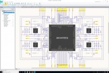
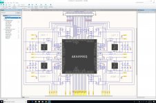
Here is a much cleaner version of the schematic, with proper grouping of ports on the North and South sides. I've also added ground ports for the audio outputs that will be routed through headers going to the XLR board. And I've marked the four hardwired ports mentioned by Mark in grey so that we do not forget about them. Last but not least, I've added some large labels for the four channels (Left 1, Right 1, Left 2, Right 2), making it easier to quickly grasp the circuit's overall geometry.
I'm starting to really like this schematic...
Attachments
Last edited:
Double or Triple Circuits
In selecting our connectors for the interconnect between the DAC board and the DAC PSU board, we should also look at the way the DAC mezzanine board is connected to the main board on the AKM evaluation setup. Some critical circuits are actually doubled or tripled:
- VREF (8 circuits): all doubled
- VSS & VDD (8 circuits): all doubled
- VOP (8 circuits): all tripled
This means that we probably need an extra 24 or 32 pins on top of the 80 that we had already planned for.
Mclk pin is at the north.
I2S/TDM buses - are at the south, and should include also Mclk.
But there are analogue circuits at the east and west - it in not a good idea to route Mclk close to analogue. So there is only one path - through the center of the chip, which is hardly to do with 2 layer PCB.
It's probably because MCLK is more sensitive, and the I2S / TDM / serial interfaces aren't critical.
I think ESS has a similar layout? The MCLK doesn't need to cross the chip if you place it on the north side.
With a multi-layer board you can bury it and run it as stripline if you felt like it. I don't think a 2 layer board is appropriate for this DAC. I wouldn't even do a 2 layer board for a low-end device, it's just not worth my time in routing and optimization to get 2 layers to work given the low prices of 4 layer boards these days.
In selecting our connectors for the interconnect between the DAC board and the DAC PSU board, we should also look at the way the DAC mezzanine board is connected to the main board on the AKM evaluation setup. Some critical circuits are actually doubled or tripled:
- VREF (8 circuits): all doubled
- VSS & VDD (8 circuits): all doubled
- VOP (8 circuits): all tripled
This means that we probably need an extra 24 or 32 pins on top of the 80 that we had already planned for.
It depends what connectors you are using as to how many conductors you should use for power, but multiple is a good idea. You should have a ground pin for every power pin. I normally prefer to have a ground pin adjacent to every single pin on the connector also, for EMC reasons. So, you could do something like:
S S S S S S S S S S S
G S G S G S G S G S G
Since we need so many pins, and since we're going to get our critical signals coming from the MCU through ERF8/ERM8 connectors already, I figure that we should use ERF8/ERM8 connectors for the DAC board as well, because the ERF8/ERM8 interconnect is already the weakest link in the chain. And by doubling or tripling certain circuits and having ground pins everywhere, we should be fine.
In terms of layout, I was even thinking about something like that:
Code:
G S G S G S G S G S G S
S G S G S G S G S G S G
"All your pin are ground to us"
Shielded Connectors
In order to improve the connectivity between the DAC board and its PSU board, we will try to use the Samtec ERF8-S and ERM8-S shielded connectors. We will use the 30-position (60-circuit) version, which will give us 120 circuits (we need a minimum of 112 in order to provide one ground return circuit per signal circuit). And we will pick the 16mm mating height version, which will give us plenty of room for our 11.9mm E12 capacitors and some low-profile components on the other side. And we'll use the 30 µ" gold plating version. These won't be cheap, but they should provide the best option for the very tight space constraints that we have to deal with.
In order to improve the connectivity between the DAC board and its PSU board, we will try to use the Samtec ERF8-S and ERM8-S shielded connectors. We will use the 30-position (60-circuit) version, which will give us 120 circuits (we need a minimum of 112 in order to provide one ground return circuit per signal circuit). And we will pick the 16mm mating height version, which will give us plenty of room for our 11.9mm E12 capacitors and some low-profile components on the other side. And we'll use the 30 µ" gold plating version. These won't be cheap, but they should provide the best option for the very tight space constraints that we have to deal with.
Connector Schematic
Here is a first version of the connector schematic for the North side. Using a Samtec ERM8-S connector with 30 positions (60 circuits), we've managed to:
- Triple all VOP circuits
- Double all AVSS circuits
- Double all VDDL circuits
- Double all VSSL circuits
- Double all VREF circuits
- Double AVDD pin 107
- Double AVSS pin 106
- Add a DVSS pin for every digital signal pin
- Dedicate pins for LDOE, PSN, CAD0, and CAD1 (just in case)
And with all that, we do not have a single pin to spare...
We're now matching exactly what is done by AKM's evaluation board.
Also, all the DVSS pins added to every digital signal pin follow the zig-zag pattern mentioned earlier:
I'm actually quite happy about how this all turned out...
Now working on the South side.
Here is a first version of the connector schematic for the North side. Using a Samtec ERM8-S connector with 30 positions (60 circuits), we've managed to:
- Triple all VOP circuits
- Double all AVSS circuits
- Double all VDDL circuits
- Double all VSSL circuits
- Double all VREF circuits
- Double AVDD pin 107
- Double AVSS pin 106
- Add a DVSS pin for every digital signal pin
- Dedicate pins for LDOE, PSN, CAD0, and CAD1 (just in case)
And with all that, we do not have a single pin to spare...
We're now matching exactly what is done by AKM's evaluation board.
Also, all the DVSS pins added to every digital signal pin follow the zig-zag pattern mentioned earlier:
Code:
D S D S D S D S
S D S D S D S D
I'm actually quite happy about how this all turned out...
Now working on the South side.
Attachments
Last edited:
- Home
- Source & Line
- Digital Line Level
- 8 × AK5578EN + 8 × AK4499EQ ADC/DAC Boards