Instead of red dots, if CS has it, I recommend you place a Generic No ERC directive. That’s the correct way to handle NC pins in Altium, anyway.
Nice! Exactly what I was looking for. I just did not know what to call it. Here is the documentation for it.
Thanks a lot Chris.
Schematic updated...
Attachments
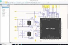
Are C81 / C85 and 82 / 86 suposed to be gnd connected?
WRT opamps and DAC chip symbols, aren't there standard online circuitstudio libraries?
WRT opamps and DAC chip symbols, aren't there standard online circuitstudio libraries?
My workshop is in a garage, so loudspeakers would not sound great.
Nearfield monitors will be fine and can sound excellent.
Despite what others may say, I encourage you to do as much listening as
possible, it really adds a lot of enjoyment to the whole process.
Who doesn't want to listen to something they are building and tweaking?
I'll go into this a little more later. Work to do.
T
Are C81 / C85 and 82 / 86 suposed to be gnd connected?
WRT opamps and DAC chip symbols, aren't there standard online circuitstudio libraries?
Great catch! I fixed them in the new revision. Will post tomorrow.
AS far as libraries are concerned, I usually prefer to build my own. It makes schematic more consistent.
Nearfield monitors will be fine and can sound excellent.
Despite what others may say, I encourage you to do as much listening as
possible, it really adds a lot of enjoyment to the whole process.
Who doesn't want to listen to something they are building and tweaking?
I'll go into this a little more later. Work to do.
T
I will do a ton of listening, no need to worry about that.
Complete Schematic
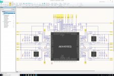
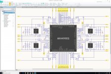
Here is the complete schematic for the DAC board.
The North side has been cleaned up a bit.
Clearly, this was quite a bit more work than I had originally expected. Each channel requires quite a few components, and having four channels means that we have four times more components to deal with (only nine components are channel-independent).
Now, we need to figure out the interconnect topology with the PSU board.
Attachments
Local LDO regulators for the dac chip digital functions?
I would be great if we can fit them on the board, but I'm not sure that we'll have any room for it. I need to start working on the PCB layout before I can answer that question. I'll start on that tomorrow.
Mclk too? 🙂
Alex,
I fail to catch the joke. Or did I make a mistake in the schematic? Can you explain? Sorry, I'm slow before my first coffee of the day...
Last edited:
Pin 108 - Mclk, it is located at the opposite side to all other I2S/TDM signals.
Oh yes, I remember now. Indeed, not the best decision...
It’s probably necessary for performance.
Internally to their circuits or in order to avoid EMI? Or both?
DAC Board Pinout
I am currently reviewing the set of pins that our DAC board should get:
- North: 19 pins
- South: 20 pins
- West: 14 pins
- East: 14 pins
On the West and East sides, we have 4 audio outputs pins (on each side) that will go up to the XLR board. Therefore, we only need 10 pins on each side going down to the PSU board.
On the North and South sides, there are some digital control pins that could be set by a SIPO shift register:
- PSN
- ACKS/CAD1
- LDOE
- PDN
- SMUTE/CSN
- DIF0/DZFL
- DIF1/DZFR
- DIF2/CAD0
- VTSEL
And the TEST pin can be connected directly to AVSS. Therefore, if we do that and use an 8-bit shift register, we can get rid of 7 pins, which means that North and South together need 32 pins. But that's not taking ground return signals into account. Ideally, every other pin would be used for that. And if we do that, we can get rid of the dedicated AVSS and DVSS pins.
If we do that, we need 30 + 30 + 20 pins, for a grand total of 80 pins, which could be offered by two 40-position connectors. The question then becomes the following: could we use ERF8/ERM8 connectors for that, or are we better off if high-quality 0.10" headers?
Last edited:
On the North and South sides, there are some digital control pins that could be set by a SIPO shift register:
The MAX7328/MAX7329 I²C port expander could be used for that purpose.
- Home
- Source & Line
- Digital Line Level
- 8 × AK5578EN + 8 × AK4499EQ ADC/DAC Boards