Less chuffing from a wider port is the reason I'd go that way, but whatever works for the builder!

Correct, but to reduce required space and push resonances up (possibly out of the woofer pass band, probably impossible in this case) it can be useful to reduce cross section in the middle of the port by using a curved port geometry.All things equal, the wider the port the less chuffing though.
ZDR, I thought you are doing MTM? That would make more sense to me, personally I don't like 2.5 way unless you are using linear phase dsp filters.
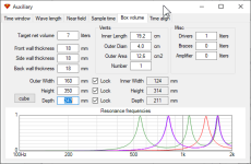
Nice metric with the port air velocity! 👌 Is that for 2 woofers? I'm wondering if anyone knows how the limit of 17m/s was derived?
One thing I would point out (OTT for this thread really) is velocity is not turbulence. Changes in velocity between parallel air streams cause turbulence. What we really want to know is the Turbulence Kinematic Energy TKE. In CFD sims I've seen cases of lower average and max. velocity, yet higher TKE when adjusting port geometry.
Don‘t focus too much on port chuffing. These drivers will have other trouble if you push them to ‘chuff the port’. I’d put my money on reducing port resonances.
I guess it's 2 way with woofers in parallel, afaik? I did not decide for an arrangement yet, MTM or TMM...
The screenshot above is intended with woofers in parallel connection. Do not consider its values if you want to connect them in series.
I guess most of us would do a TMM in a 2.5-way crossover, aiming the lowpass of the lower woofer on the baffle step function of the cabinet.
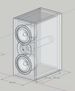
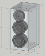
Provided the drivers can be that close in reality, yes that looks good. I'd put the port off-center to one side - it will avoid the back of the drivers but also have less unwanted resonances. Add some bracing between opposite panels too.
Oh no, that's a bad idea 😵
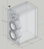
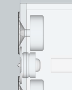
Sink 'rebate' all drivers. Your woofers already have a flat side, so use those to get the woofers close to the tweeter. Use the waveguide I shared to also give you a flat edge for the tweeter to join the woofers. The waveguide will also make the time alignment of the tweeter and woofers correct so the crossover will be easier.
Cut the rectangle for the tweeter waveguide. Then cut the circle for the woofers. (EDIT: I just realised of course the bottom of the woofers is also flat so my drawing is not exactly right.
How am I supposed to install the waveguide? By removing existing faceplate? Isn’t that attached to membrane and the coil?
- Home
- Loudspeakers
- Multi-Way
- 8 Excel W12CY001 looking for a DIY project to fit in