I thought that in current mod is involved some current generator with feedback what output impedance is not same as for voltage output.What kind of difference were you expecting? just curious.
basically I think it boils down to the dac output stage having a much easier time, driving a biased virtual ground node and having the opamp (or whatever) take care of the conversion, rather than being loaded with a higher impedance. So distortion is lower.
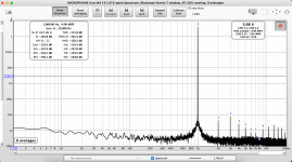
Hooked up the Ian Canada I/V stage on my spare ES9016 and definitely got improved THD performance. Originally tried with the stock op amps and was getting around -106 dB THD, swapped those out for some OPA1612s I had planned to use with Ian's I/V and got the limits of my measurement rig at around -109 dB to -110 dB. For reference I was getting around -104 dB on the stock I/V stage. It also seems like the turn on / off pops are lower than I remember based on measurements but did not want to risk actually listening to the turn on / off pop, will need to investigate this further.
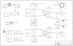
My only complaint is full scale output voltage from the balanced outputs is 1.99 V. I'm very much a noob on I/V stages but I believe this means I need to raise the value of the feedback resistors. I believe in Ian's design these are the 1.62K resistors at positions R1/R2, R16/R17, R19/R20, R33/R34, as these resistors are in parallel any reason I couldn't just remove one resistor from each pair to increase the output voltage? I've re-attached the schematic for reference.
I've attached a screenshot of the FFT from my MOTU M4 with OPA1612s. I have a Cosmos ADC on the way which should allow for more meaningful comparisons of noise and THD.
Kind of tempted to try out Ian's I/V stage on the ES9038 as I am not doing anything with that board but have not decided yet.
Michael
Attachments

Are R36-39 fitted? these should not be there at all ... not for ESS anyway. So THD+N is still pretty bad, but definitely better. I guess thats noise still limited by your MOTU as disussed.
I wouldnt just remove R1/R2/R16/R17, or R19/20/33/34 although you certainly could, that would result in a little bit hot output. around 5.9Vpp, or ~4.2VRMS. I presume by 2V you mean RMS? not peak to peak?
I wouldnt just remove R1/R2/R16/R17, or R19/20/33/34 although you certainly could, that would result in a little bit hot output. around 5.9Vpp, or ~4.2VRMS. I presume by 2V you mean RMS? not peak to peak?
Last edited:
lol, dont mind me. my brain isnt working. I was only looking at the first stage. the output filter will drop a small amount, but the numbers should still basically hold.
Short answer = Yes, if your amp is fine with double that 2V. If those input resistors are present; remove/short them.
R36 to R39 were added along with input film caps at some point to help filter out dac noise from producing EMI effects in the I/V opamps. Caps are for the noise, resistors are to limit resultant gain peaking in the I/V circuit that would otherwise occur due to the input capacitance. Downside is an increase is measured distortion, while audible EMI-related noise/distortion may be reduced. Allo similarly found that opamp EMI sensitivity in both I/V and differential summing stages produced audible effects that at least in part tend to show up as noise on FFTs. Minimizing measured noise is one approach that does not require reliance on listening tests. Allo also found that reducing measured distortion to numbers lower than ESS datasheet values was possible but doing so had an adverse subjective effect on SQ. Note: Some or all of the above is not published information.
EDIT: Regarding I/V gain setting feedback resistors. Changing their value is an easy way to adjust voltage gain. However, measured noise and or distortion may be affected by using non-optimal values. Also, in theory if I/V feedback resistors are changed then changing feedback caps to maintain filter time constant may be worth considering.
EDIT: Regarding I/V gain setting feedback resistors. Changing their value is an easy way to adjust voltage gain. However, measured noise and or distortion may be affected by using non-optimal values. Also, in theory if I/V feedback resistors are changed then changing feedback caps to maintain filter time constant may be worth considering.
Last edited:
Oh I know what they are for, but its a trade off and myself, for an ESS dac, I would always avoid the resistors and use an opamp fast enough to deal with the glitch energy, then tweak the feedback caps. damned if you do, damned if you dont I guess.
side note; its always possible to beat ESS datasheet performance by a bit. their boards are functional, but certainly not exceptional. That being said, that isnt going to happen with this board, regardless of the IV stage you tack on.
Its not just glitch energy. There is also the issue of EMI demodulation in input transistor junctions and or ESD protection diodes. Newer opamps like OPA1612 and OPA1556 are specified (not necessarily published on the datasheets) for EMI tolerance at the inputs. Otherwise there is no way even a 50MHz GBW opamp is going to handle clock edge frequencies buried in the dac output noise but still there. Even the most suitable opamps seem to produce a little bit of audible effects but at least the effects are very attenuated. In a low noise reproduction system there is a simple test that sometimes can show how effective filtering is: Turn down the digital volume before the dac to very low level (experiment with level), then amplify up the analog output. IS it just low volume, low distortion audio and a little hiss noise, or maybe some weird noise/distortion that is signal dependent? A good test track is Janis Ian's, Breaking Silence. It has loud punchy dynamics followed by quiet room decay sounds that go on and on. Just the kind of thing modulators don't always handle very well due at least in part to settling time of state variables after volume transients (the settling effect which was described by Martin Mallinson, ESS VP of engineering). That garbage should get filtered out since most of it is really in the RF. At least it was until the electronics demodulated it. To be clear, my investigations have been limited and are ongoing. What I express above is nothing more that an opinion based on limited observations so far. Opinion is subject to change over time.
Last edited:
hmmm, yeah, I cant say ive ever encountered this problem, listening with opa1632, or opa1612/buf634 and high end in ear monitors. If so, just use a nice fet input opamp; problem solved.
Last edited:
or a discrete fet IV, but thats OT.
also, I think perhaps designing a situation where you will accentuate 'problems' is not a very good test to highlight actual problems.
also, I think perhaps designing a situation where you will accentuate 'problems' is not a very good test to highlight actual problems.
If using DSD there are still full scale RF pulses coming out of the dac. Perhaps more challenging than PCM?
perhaps. I dont use DSD content and ESS does not really parse it anyway. I use digital volume control (with headphones) and digital crossover with speakers, as does Michael.
DSD is a long way down the list of priorities for me, since the above represent far more value, to me.
DSD is a long way down the list of priorities for me, since the above represent far more value, to me.
Thanks for the input guys.
Not sure how much time I want to spend on this, to me this experiment was more to see how much I could improve measured performance by using an external I/V stage or if the DIYINHK board layout would be the limiting factor. As mentioned the MOTU ADC is very limiting from a noise perspective so it is not possible to evaluate any potential change in noise performance, I'll need to wait for the higher performance ADC to arrive to properly evaluate. Similarly I've never gotten better than -109 THD with the M4 even when using a DAC with super low THD like the Okto dac8 pro so although THD has improved I am at the limit of the M4 ADC.
Regarding output voltage, I am getting 1.99 vrms and would prefer to get something closer to 4 vrms. It sounds like there are two options being discussed to accomplish this, 1) remove and short R36-R39 (input resistors) or 2) remove R1/R16/R19/R33 (feedback resistors), is this correct?
Michael
Hey mate. nah, 1) will have no effect on the output voltage, or very little anyway. 2) will give you what you want. as its just an experiment you can probably safely ignore 1) distortion performance will be slightly worse with them in place and I personally would remove them, but its not a huge deal. with 2) you will need to adjust C1/12/15/22 for matching filter response, but that also can be safely ignored if just as an experiment.
You can safely ignore Mark's pontification on RF demodulation too IMO 🙂 You know my opinion on this dac and I would not blame you at all for just putting it aside right now.
You can safely ignore Mark's pontification on RF demodulation too IMO 🙂 You know my opinion on this dac and I would not blame you at all for just putting it aside right now.
Thanks again, popped off the feedback resistors and now sitting at 4 V 🙂. 3rd harmonic increased quite a bit but overall THD did not get worse. I also hooked up some garbage speakers to see about turn on / off pop, definitely way less than the stock I/V stage. Not pleasant but not scary.
Ugh, thought I was done with this thing but now I can almost see it being useful. Still think the cost is nowhere worth it once you add power supplies, case, I/V stages, op amps, etc but might have to get a few more I/V stages and do something with it.
Michael
Ugh, thought I was done with this thing but now I can almost see it being useful. Still think the cost is nowhere worth it once you add power supplies, case, I/V stages, op amps, etc but might have to get a few more I/V stages and do something with it.
Michael
Attachments
Oh, wow, that is overall quite a difference from the stock IV stage.Thanks again, popped off the feedback resistors and now sitting at 4 V 🙂. 3rd harmonic increased quite a bit but overall THD did not get worse. I also hooked up some garbage speakers to see about turn on / off pop, definitely way less than the stock I/V stage. Not pleasant but not scary.
Ugh, thought I was done with this thing but now I can almost see it being useful. Still think the cost is nowhere worth it once you add power supplies, case, I/V stages, op amps, etc but might have to get a few more I/V stages and do something with it.
Michael
How did you connect the ground planes? And how much AVCC bias? AVCC/3? My IVY IIIs. don;t have any AVCC bias at all. Maybe its not necessary because they use the 0PA1632? No clue.
I'm so tempted to buy a Cosmos ADC to measure them, but I have just bought new Viawave tweeters and Scan Speak woofers for my - never to be finished - speakers. So that will have to wait.
Thanks for all your work, they measure close to the datasheet specs now. I'm impressed.
- Home
- Source & Line
- Digital Line Level
- 8-channel DAC + board for low-power application