AVCC is applied at the dac board only. The connector between the dac board and the output stage board caries the AVCC voltage from the dac to the output stage board where it divided by 3 to produce Vref....So in terms of supplying AVCC to Ian's board and the DAC I assume that I just split it at the regulator output?
AVCC is applied at the dac board only. The connector between the dac board and the output stage board caries the AVCC voltage from the dac to the output stage board where it divided by 3 to produce Vref.
But on these DIYINHK DACs the only accessible connection for AVCC is at the power supply connection. As discussed above there is not an AVCC connection to the onboard I/V stage. I guess maybe I could grab it from the DAC pins but not sure I am up for soldering something that small.
Michael
If using Ian's output stage board with a diyinhk dac, it matters that the ground planes are connected together with a very low impedance connection. A simple wire is not very good for that. Regarding application of AVCC voltage, the regulator output could be split between the various places it needs to go. The diyinhk dac board I got had separate connections for AVCC_L and AVCC_R, since it helps to use two regulators in order to help optimize stereo separation. However, Ian's output stage and dac are (unfortunately) designed to run from a single AVCC supply. In that case it only makes sense to use one AVCC regulator and tie all the loads together. As to AVCC return grounds, it might be better to connect that from the regulator to the dac ground plane at a single point. Otherwise multiple ground loops will be created.
Thanks. Sounds like I can split at the regulator but may need to play around with grounding, more than happy to experiment a bit.
These boards only have a single AVCC connection so I don't feel too bad about using the Ian board. Also do not really plan on using this DAC for anything serious as I have other better performing multichannel DACs, more just a curiosity at this point.
I'll see what I can do this weekend and post some measurements.
Michael
Will you use the ES9016 or the 38? VRef for the ES9038 is not AVCC/2, but 1.3V, don't know for the 16.Thanks for the info guys, I have a slightly newer version of the I/V, the schematic for which can be found here -> https://github.com/iancanada/Docume...acHAT/IVboards/IVSTD/IvStdMkII_ManualV2.0.pdf.
I assume Vref is the AVCC bias and based on the voltage divider looks like it is set to AVCC / 3.
So in terms of supplying AVCC to Ian's board and the DAC I assume that I just split it at the regulator output?
I'll give it a try this weekend and see how it goes.
Michael
Mind that you may have to adjust the feedback resistors, I don't know on what output current Ian's design is based. For the ES9038 on the IVY-III I had to use 4 times lower resistance than for the ES9016, as it has approx 4 times higher current.
Last edited:
I’ll try both although as you mention I am sure I will need different feedback resistors.
Is there any issue with leaving the 1 uF film capacitors and the op amp sockets on the board or should I remove them? I guess I can test it as I have a fully populated ES9016 board but also have a bare one so I can see if there is any difference.
Michael
Is there any issue with leaving the 1 uF film capacitors and the op amp sockets on the board or should I remove them? I guess I can test it as I have a fully populated ES9016 board but also have a bare one so I can see if there is any difference.
Michael
no, the film capacitors just decouple the 12V lines, they can stay. But you'll need to remove the smd cap and resistor to ground near the opamps, the will mess up the DAC-B lines (and you have to remove the opamps themselves of course). Good luck with it, curious how it will work out.I’ll try both although as you mention I am sure I will need different feedback resistors.
Is there any issue with leaving the 1 uF film capacitors and the op amp sockets on the board or should I remove them? I guess I can test it as I have a fully populated ES9016 board but also have a bare one so I can see if there is any difference.
Michael
Thanks for the info, in that case I will definitely start with the bare ES9016 board and go from there.
Michael
Michael
The unpopulated filmcaps holes give a nice acces to the ground plane under the dac-channel traces to their origin. Anyway, that's how I connected the ground between the pcbs. Routed this ground, and the corresponding 2 dac channels in a single shielded twisted pair wire.Thanks for the info, in that case I will definitely start with the bare ES9016 board and go from there.
Michael
Quite a lot of wires, but doable (locking jst-connectors or direct soldering).
yes, on the ESS app note it calls for around 1.3V for 9038, but this was published before the rather significant investigation into the hump and its origins. I would not set it at 1.3V personally. To avoid the hump completely; I would tend to use just lower, more like AVCC/3, or 1-1.1V. With a dual mono 9038pro for example, syn08 ended up successively lower and lower, finishing with more like AVCC/4 or around 850mV before the distortions vanished below the noise, to create the best measuring ESS dac ive seen. not that 1.3 will create audible or easily measurable distortions, depending on your measurement gear; if you have access to a high performance ADC, notch filter and LNA. if you do go low, make sure your opamps and their power supplies are able to deal with the extra current as they will make up the difference. for an 8 channel DAC a 500ma power supply may not do.
definitely do not rely on jst connectors.
definitely do not rely on jst connectors.
Do you know why ES9038Pro max output current is calculated from voltage mode output impedance? Same it is for ES9016.@kaameelis
..
the 9038 board outputs about +/-15ma, so depending on the opamp used, this, along with having to source some of the dac current too, mean that some will be operating outside their capability. with the 9016, the current is much smaller (about 4 times), so the opamps will handle it comfortably. I cant remember how profound the difference in performance was with driving a virtual GND at 0V vs biased, but it was significant. its unknown quantity makes it difficult to describe the whole theoretically.
Attachments
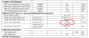
that would be how I came up with +/-15ma per channel (its 202Ω per phase)... output impedance of 202Ω. AVCC voltage is 3v3 x 0.924 = 3.0492, or 3049 mV / 202 = ... drumroll +/-15.095mA
its plain ohms law, of course thats how you figure it out. shouldn't need a datasheet to tell you thats how you calculate it.
sorry. I shouldn't be touchy; my apologies, I didnt get a lot of sleep last night, the cicadas are going nuts here at the moment..
how do I know? at its heart, the ESS dacs are really voltage out dacs. thats how they were initially designed and specified. they just found that if set up in this rather specific way, they behave like a current out dac and this makes them perform quite a bit better. they were already good, but this made them the best objective performance parts around for quite some time, until the AK4499. very low impedance for a current out dac really. typically a current source is much higher impedance. there is no 'current mode' and 'voltage mode' the VOUT is basically just AVCC minus losses (an oversimplification, i'm sure someone will chime in 😛).
it is easier to think of the output as a voltage source in series with its output impedance rather than a 'voltage dac, or a 'current dac. they really need babying to make them act like a current out dac. the AKM and ROHM dacs are similarly specified though really. just seems to be the way manufacturing goes these days, because to get the performance and keep on improving it, they are doing so by adding more and more dacs in parallel on the die. thats why the current keeps on going up with each model and the output impedance keeps going down. You can think of the 9038PRO as 4 x 9018S in parallel and the 9018S was already made by running a number of dacs in parallel.
Last edited:
but really its just a simple application of ohms law. how else would you calculate the current out than dividing the voltage out by the resistance/impedance? you can calculate backwards in the same way. Ohms law really is a marvel; you should read up on it. It sounds like this is the first thing you should do, before you do/build anything else; it is essential knowledge.
Last edited:
If current in current output mode is calculated directly with Ohms law from voltage ouput impedance then there is not real differenc in current and vlotage mode output configuration?
No difference in the voltage, no, as ive already mentioned. the voltage and the VGND point are the same either way. running in 'current mode' just allows cancellation of some of the internal distortion mechanisms/non-linearities, so you end up with lower distortion. Without insider knowledge I cant give more detail than that on exactly what distortion mechanisms, or exactly how they are cancelled, but it is easily objectively verified.
I hate these terms 'voltage mode' and 'current mode' and really wish they hadnt entered the DIYA lexicon. they lead to quite a bit of confusion. its the same dac; it doesnt have a switch. there would be no reason to expect ohms law to fail, or for the numbers not to 'add up' the same way.
*well hmm, not totally true. its true if just talking passive IV, but if you set the dac up as 'current mode' and that current is buffered by an active stage, depending on the resistor value you choose for RIV, you can swing a lot more voltage than 3V. if just running 'voltage mode' with passive IV, or a voltage buffer, the dacs power supply rails limit the amplitude of the voltage it can put out before clipping. with active IV, you are limited by the voltage rails of THAT stage before clipping.
Last edited:
What kind of difference were you expecting? just curious.
basically I think it boils down to the dac output stage having a much easier time, driving a biased virtual ground node and having the opamp (or whatever) take care of the conversion, rather than being loaded with a higher impedance. So distortion is lower.
basically I think it boils down to the dac output stage having a much easier time, driving a biased virtual ground node and having the opamp (or whatever) take care of the conversion, rather than being loaded with a higher impedance. So distortion is lower.
Last edited:
Maybe not. Rohm refers to their dac as being of the 'current segment' type. In dac parlance 'segment' probably refers to a segmented architecture, something that appears to be consistent with the Rohm dac's several differently named AVCC pins. Also 'current' in this instance may refer to using switched current sources rather than switched resistors. Both are considered basic dac output types. Thing is, for best measurements resistor-based seems be the winner. So why would somebody design a current-source based dac? Maybe there is an engineering tradeoff? Better subjective sound? More options for output stage design?....ROHM dacs are similarly specified...
https://www.analog.com/media/en/training-seminars/tutorials/mt-016.pdf
Last edited:
yeah, just more robust for options on the analogue output working with them as current sources.. while ESS and AKM are great and you have a few options; they are somewhat limiting if you want to get the best out of them. yeah I should have left ROHM off the list, my memory is foggy and I never followed through with the build. too many things on the go to add another was just spreading my resources too thin and its only 2 channel, so I would have needed 4 ... $$$. its output R is not as low either, but I honestly dont remember the details of it all that well; so happy to just take any corrections you make on the chin 🙂. My memory works better with things once i've applied them; thats just how my brain works. if I dont apply knowledge, it vanishes from my memory much more easily.
its output Z was more like 1.2K or something, wasnt it? cant be bothered looking up the datasheet at the moment.
- Home
- Source & Line
- Digital Line Level
- 8-channel DAC + board for low-power application