Just for sake of information, I posted in the gallery the completed project somehow related with the object of thread.
Now running also with anodic CCS (and led+120ohm below).
The current through the driver is about 1.9mA, I was wondering if it was possible to use a cascoded DN2540 depletion mosfet instead of the standard CCS. However, it seems to me that I have read that for a correct working it must be Ia > 3.3mA. I ask for clarification on this ...
So after making so much noise regarding LED's in the cathode circuit. I guess some might say,
'OK. weise guy, what would you do'. I'd take that LED out as soon as the soldering iron got to operating temperature.
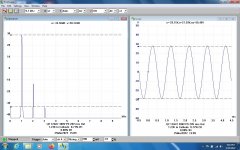
And replace it with a common resistor. Here are the results of doing just that with a 1.23K cathode resistor.
The gain is about 3db less, but still plenty to drive many common output tubes.
And the D% has dropped significantly. The Rk will also stabilize the operating point as the tube ages.
And there is plenty of room to add full NFB if needed.
The attachments shew D% results on the bench, both the cathode return as original & with the LED pulled out.
Something to think about. What about in the cathode of a power output?
Depends on which kind of distortion we like beas!
'OK. weise guy, what would you do'. I'd take that LED out as soon as the soldering iron got to operating temperature.
And replace it with a common resistor. Here are the results of doing just that with a 1.23K cathode resistor.
The gain is about 3db less, but still plenty to drive many common output tubes.
And the D% has dropped significantly. The Rk will also stabilize the operating point as the tube ages.
And there is plenty of room to add full NFB if needed.
The attachments shew D% results on the bench, both the cathode return as original & with the LED pulled out.
Something to think about. What about in the cathode of a power output?
Depends on which kind of distortion we like beas!
Attachments
10dB difference of 2nd harmonic and over 6dB difference in 3rd for only a 3dB difference in gain? Again I worry about the valve being operated at different bias'. Assuming an improbably large cathode current of 1mA, 1K23 Ohms is a -1.23VDC bias, compared to somewhere North of 1.6VDC across the LED alone. The disparity between your results here and those in post #79 make me worry about apples-to-apples generality (although obviously applicable to the specific circuit).
Thanks as always,
Chris
Thanks as always,
Chris
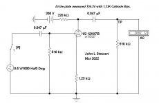
The drop across the plate resister is 174V, so Ip is 1.45 mA.
1.45 mA in Rk of 1.23K is ~1.78V.
The LED design had very little cathode resister NFB. plus the non-linearity of the LED.
Adding local NFB & dumping the LED makes quite a difference.
But I’ll take a look anyway. The soldering iron is hot & waiting for me!!
1.45 mA in Rk of 1.23K is ~1.78V.
The LED design had very little cathode resister NFB. plus the non-linearity of the LED.
Adding local NFB & dumping the LED makes quite a difference.
But I’ll take a look anyway. The soldering iron is hot & waiting for me!!
OK Chris, here are the results of the most recent episode of the 6SQ7 bare bones amp.
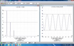
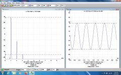
This time with a 1.8K cathode resister. The drop across the plate resister is 155V, so Ip is 1.29 mA.
1.29 mA in Rk of 1.8K is ~2.33V.
Gain drops a further 1.4 db. But D% is only marginally better.
I think this AX7 has run dry on 'goodness'.
All a worthwhile experiment. It probably deserves a formal report.
Something to do when the rain starts here tomorrow & the temp takes a dive.
Attachments
Very cool. Looks like your initial choice of cathode resistor value was spot on. Much thanks for doing the good work.
All good fortune,
Chris
All good fortune,
Chris
Interesting just 1/2 hour ago I soldered two green LEDs in my 12AX7 stage, on top of a 220 Ohms handling the feedback signal. Then I read through all this. Might as well solder back the 1.2k (which I didnt work out of the tube socket pin for fear of destroying it). My plate resistor is 390K, versus the 220K I see above. If I drop it to 220, will I get more current through the 1.42k composite cathode resistance?
I'd like to reduce the gain of that stage, so if the combo of reducing the plate resistor and its corresponding increase in grid bias voltage does just that, I'd be happy!
I'd like to reduce the gain of that stage, so if the combo of reducing the plate resistor and its corresponding increase in grid bias voltage does just that, I'd be happy!
- Home
- Amplifiers
- Tubes / Valves
- 6SQ7 - EL34 SE amp design