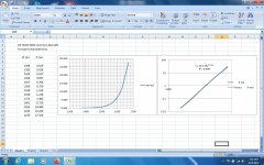
So here is the result of running forward currents thru a common red LED
picked at random from my stash of original HP parts. This one an HP HLMP 4855.
The measurement data results in a very smooth curve without the application of Cookes Variable Constant.
Both linear & log-log plots. A square law device has a slope of 2 on log-log graph. Like this one.
Will it matter in the cathode of a tube? Have a look tomorrow.
Avago is a spinoff of Agilent which in turn was a spinoff of HP, HP Opto (OED) started (~1961) as a part of
a division of HP doing research in SS devices. We also had Schottky's which at HP were called Hot Carrier Diodes.
As well as PIN Diodes. And quite few built up things like Optical Encoders, Opto-Isolaters & Numeric
& Alphanumeric display. HP was a cornucopia of advanced products. We had to run hard to keep up
with what was available to sell.😎
Attachments
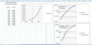
Here is another, this time a common red LED but no ID.
Just what we might get at random from a surplus house.
It doesn't fit square law or linear well. the LED appears to be in transition from very low currents
into its ohmic value region. Will it cause distortion? The 6SQ7 in this thread runs DC of 1.5 or 3 mA,
depending whether the Schade FB is connected or not. And from the DC value to +/-
whatever the signal takes it too.
Attachments
Ref: post #61
Very interesting data. Thanks very much! I eyeball this as a 9R slope at 5mA (in the knee) and 6R at 10mA (above the knee). Both of these are higher than a high mu triode will use, so this device would be operating below the knee for many applications. How much work does it take you to get this kind of data? After initial setup?
Thanks very much, as always,
Chris
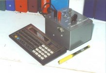
Using a simple variable constant current source to drive the LED samples, something I built about 50 yrs ago.
So setting the CC source powered up for about an hour, than set some low current to check stability.
Current & voltage are measured with separate digital meters. The LED forward voltage is measured directly
on the LED. The DVM looks like a 10M load.
The data on this run is taken from an HLMP 4955 red LED. Then into Office Spreadsheet to process the results.
The power series trend line gives the best fit. For currents from
0.65 to 1.06 mA the LED incremental resistance looks like 63.4 R
1.06 to 1.62..................... 44.64R
1.62 to 3.25.....................30.62 R
3.25 to 4.20.....................25.26 R
The cct in this thread fits that region. As the tube grid is varied the cathode current varies.
The changing current is converted by the incremental resistance to a voltage that is amplified by the mu of the tube.
That modified by whatever load is on the plate. A bit like reach thru on bipolar transistor.
Attachments

So here is the result of running forward currents thru a common red LED
picked at random from my stash of original HP parts. This one an HP HLMP 4855.
The measurement data results in a very smooth curve without the application of Cookes Variable Constant.
Both linear & log-log plots. A square law device has a slope of 2 on log-log graph. Like this one.
Will it matter in the cathode of a tube? Have a look tomorrow.
Avago is a spinoff of Agilent which in turn was a spinoff of HP, HP Opto (OED) started (~1961) as a part of
a division of HP doing research in SS devices. We also had Schottky's which at HP were called Hot Carrier Diodes.
As well as PIN Diodes. And quite few built up things like Optical Encoders, Opto-Isolaters & Numeric
& Alphanumeric display. HP was a cornucopia of advanced products. We had to run hard to keep up
with what was available to sell.😎
Interesting graph, me too I investigated a little about the characteristics for a LED to be te best choice.
Actually, I faced marginally the matter in the past here (a lot of people praised for the HLMP-6000 but I couldn't try it ever) but then I shelved.
So far, I used to stick on some "vintage" square red leds (recovered in some old appliance) since they seem to be very linear in a wide range of Id.
Now I'm almost out of stock in my house so I looked in the net and found the HLMP-4700 from a local vendor. From its specs it should be suitable to be used for low Id cathode biasing.
Using the last LED I ran the forward drop tests on I got some results as follows.
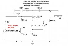
With a One KHz test tone an output of 87.8V p-p, 2.45% 2H.
Running the same cct without the LED I measured 97V p-p, 1.36% 2H.
The tube used is 1/2 of a 12AX7, very close to the 6SQ7 triode. Check the data sheets.
For a first look the LED biasing is not a good idea. Unless we like distortion.
I'll post some spectrum's later.
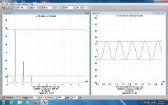
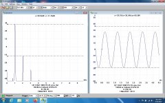
Here are spectrum's with & without a red LED in the cathode of 1/2 12AX7.
Looks like the LED causes a significant increase in 2H. The 3H is much farther down
so that THD is predominantly 2H. The cct is essentially the same as the OP for the front end of his amp.
I'll post that tomorrow.
Looks like the LED causes a significant increase in 2H. The 3H is much farther down
so that THD is predominantly 2H. The cct is essentially the same as the OP for the front end of his amp.
I'll post that tomorrow.
Attachments


Thanks again for excellent information. Just to clarify, this comparison is between a red LED (obviously not bypassed) and a (bypassed?) resistor?
12AX7 is a good stringent test, very high mu (tight grid winding pitch, low cathode work factor) and the best possible intrinsic linearity at optimum bias and loading. Distortion numbers below -50dB ref. fundamental at these output levels are possible. Red may not turn out to be the best choice for type 12AX7; maybe IR?, because of its operating voltage, which I suspect we'll need to keep above the knee for a straight enough portion of the curve.
Another possibility is to add DC current from some other source, either B+ or feedback from the output valve's anode, to force the LED into a more linear range.
Nothing is as good as battery bias, but that troubles folks' aesthetic sensibilities too much. Second best is a plain old cathode resistor, with or without added DC, but that wastes open loop gain unless integrated more thoroughly than current DIY practice.
Much thanks as always for your reality checks,
Chris
ps: I loved your recipe for making a diode curve tracer: Start with a precision current source built half a century ago. Hand record all data and massage with a customized spread sheet, to include fit-to-curve. Nothing to it!
Reminds me of the recipe for rabbit stew: first, procure a rabbit. Arf!
Very glad you're doing it,
Chris
Reminds me of the recipe for rabbit stew: first, procure a rabbit. Arf!
Very glad you're doing it,
Chris
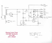
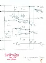
Diode Curve Tracer Schematics from the 60's, something I stuck together as a side issue in the research lab.
No photos, maybe someone put them in a museum after & left. Worked well, got fast answers on
questionable diodes. And the good ones. All from the archives.
No photos, maybe someone put them in a museum after & left. Worked well, got fast answers on
questionable diodes. And the good ones. All from the archives.
Attachments

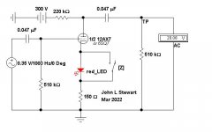
Here is the simple test setup used. The switch 'Z' in this case is nothing more than a shorting clip lead across the LED.
The SG generator is adjusted to get 20 vrms at the test point (TP), with & without the LED in cct. The PS is a regulated lab supply.
Then the FFT spectrum taken by a Pico 3224. 10 MHz, 12 bit, 2-channel FFY/Scope.
The SG generator is adjusted to get 20 vrms at the test point (TP), with & without the LED in cct. The PS is a regulated lab supply.
Then the FFT spectrum taken by a Pico 3224. 10 MHz, 12 bit, 2-channel FFY/Scope.
Attachments
That's quite a change in bias for the valve. Maybe a more apples-to-apples test would include a big cap in series with Z. But it looks pretty straight forward to duplicate. Thanks very much.
All good fortune,
Chris
All good fortune,
Chris
Hey Chris, of course you are correct. I figured I could get basic data needed without adjusting bias as long as the operating point
didn't move far enough to changes output level & D% a lot. To do that the signal level needs to be restricted, altho in this example
the 20 vrms (28V Peak) is enough to drive most common power tubes. So in the case of the 1N4007 in the test I've just run the
Q point moves from 105V with the diode in to 88 vols without. I'll have a look at another LED later & adjust the bias.
I'd originally planed to stuff a 1.5V cell into the grid to fix for the LED removed. That way Rk can remain the same.
So here is the latest, a 1N4007 in one test & a 1N34A in the other. All makes me wonder why we do this at all,
given it adds yet another part & in every case sofar increases distortion.
Before I got going I tried Googling to find if the work had already been done but came up empty.🙂
Attachments
Many thanks for the tests, results and discussion. So far:
- LEDs and other diodes delivering cathode bias can introduce measurable increases in distortion when passing bias current below their ohmic region (below the "knee").
- The amount of additional distortion depends on the diode used and is predominantly 2H.
- The increase is readily measured when the valve is delivering sufficient signal to drive common power valves to rated power.
- The results may (or may not) offend (or please) the constructor/listener.
- Constructors of the 6SQ7/EL34 amp can have fun finding out 🙂
- measuring LEDs in a manner similar to jhstewart9;
- employing infra-red LEDs to bias the input valves of phono amps. These draw 15-20mA cathode current (in the LED ohmic range) and were a good experience.
- employing a series string of HLMP6000s to bias the output valve in a single-ended pentode amp - good until low frequencies were amplified, in which case distortion was large and unpleasant. Caveats: I did not persist with the experiment to find LED-solutions but resorted to a by-passed resistor; and I have not tried diode bias in a push-pull output stage.
Folks with a completed amplifier can test the actual effect, weighted by its relative importance in the actual design, by temporarily bypassing the diode with a big capacitor. "Big" here would mean X-sub-c an order of magnitude smaller than the diode's slope. Maybe 1R at 1kHz, = 160uF, or bigger, or somewhat higher frequency.
If it proves to be significant, the LED could be biased up the curve with a trickle of extra DC from somewhere convenient, maybe the output valve's cathode.
All good fortune,
Chris
If it proves to be significant, the LED could be biased up the curve with a trickle of extra DC from somewhere convenient, maybe the output valve's cathode.
All good fortune,
Chris
One could also use a large value resistor from the plate supply to increase the bias on the diode.
Tested at 5-6W at reasonable distortion levels as I recall.What is the approximate expected watt output for this circuit ?
Tests shew that at the same operating condition the D% of the 12AX7/6SQ7 frontend
is about the same whether LED biased or biased by a single 1.5V cell.
I would put the results of these tests on diodes in the cathode circuit in the category of
"May as Well Know'. I couldn't find any data regards this on the web, so looks like might be OK.
In this particular case, anyway. Before the test cct is recycled I'll have a look at other LED colors. Later.
The test cct switches are nothing more than clip leads.
Attachments


Nothing is better than real info. Thanks as always for your commitment to fundamentals. I took a road trip today to a couple of the sites of the Paul Klipsch Museum a few hours away from home; set up a couple turntables for exhibits, had a yummy but frightening lunch "downtown" (nobody, without a single exception, wore a mask, even me - well, there it is.) Same little town is the home of Bill Clinton, pop: about 10k. One of the Museum sites is next door to the WJC birthhome, yada yada. Small town stuff.
Made me think about how much small town stuff is getting lost so fast these days. We don't always trust each other to be acting civilly, and everyone has to be effected by our civil discord like it's its own virus. I first met Paul Klipsch in 1974 (or maybe 1975 - "if you can remember, you weren't there"). He was a childhood hero, and didn't disappoint. PWK was dedicated to actual, measurable truth, and let the chips fall.
May we all subscribe to that goal of seeking the raw truth. How significant is a forward-conducting diode in the signal path? Seems like a question needing asking; it's obviously a known non-linear element, as opposed to the known very linear elements like coupling capacitors that folks love to expend brain cycles compulsing over. Good to know that even the difficult case of a high mu triode providing large-compared-to-B+ output voltages and low LED bias current bias still can fall into a category of "below my pay grade to worry about".
Not everything can or need be made perfect. In these new War times, let us remember the small town virtues to which we aspire,
And may the Goddess bless us, every one,
Chris
- Home
- Amplifiers
- Tubes / Valves
- 6SQ7 - EL34 SE amp design