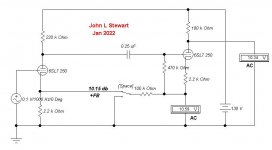
Yeah I started with an old schematic (Sun audio/JC Morrison 300B) and photoshopped "cloned" parts around to create this unique design because I thought the look of that old school schematic looked cool 🙂 AFAIK, there aren't any 6SQ7 designs like this out there for a HiFi amp. At least I never found any.
I have DM'd Stephi on their website about this , but I figured I would post my issue here as well for more clarification and documentation....
I am purchasing parts to build one of these, but stupidly purchased a 4 ohm set of output transformers.... I really wanted the 8 ohm but now it's too late and return shipping is far too expensive. Aside from a loss of overall power, is there any other drawbacks to using these trannys?? Would I require a modification in the schematic? Tia
I am purchasing parts to build one of these, but stupidly purchased a 4 ohm set of output transformers.... I really wanted the 8 ohm but now it's too late and return shipping is far too expensive. Aside from a loss of overall power, is there any other drawbacks to using these trannys?? Would I require a modification in the schematic? Tia
It's good to keep in our minds that loudspeakers are not even very close to being resistors, although it's easier to think about things as if that were true. The real world is messy and difficult to model, so we look for our lost keys under the streetlamp where the light is better, and irrespective of where we lost them.
In general, audio amplifiers behave better into lighter loading in all respects other than peak output capability. Halving the load demands (twice the load impedance) typically costs maybe 2dB peak output capability (3dB for a perfectly stiff voltage source, 1dB or less for more inherently matched impedances).
Almost universally overlooked here in diyAudio/tubes/valves is an amplifier's source (output) impedance's effect on system frequency response. We humans easily hear fractions of a dB frequency response differences over critical ranges, amounts less than caused by commonly seen amplifier source impedances feeding real world loudspeakers. But instead of dealing with that, we discuss coupling capacitors. But the light is prettier.
All good fortune,
Chris
I agree with Chris H on the p-p NFB, Not a good load for a hi mu triode.
But OK when used on a common audio Sharp cut-off pentode.
Has anyone ever tested for THD & IMD with & without that LED in the cathode.
It is a square law device in the FB path of a 3/2s power tube.
Should generate some interesting distortion products.
But OK when used on a common audio Sharp cut-off pentode.
Has anyone ever tested for THD & IMD with & without that LED in the cathode.
It is a square law device in the FB path of a 3/2s power tube.
Should generate some interesting distortion products.
It should be fine and depending on the speaker might work well. Many speakers dip down close to 4 ohms at some point so I wouldn't sweat it. It will probably have lower distortion as well. Let me know how it works out for ya.I have DM'd Stephi on their website about this , but I figured I would post my issue here as well for more clarification and documentation....
I am purchasing parts to build one of these, but stupidly purchased a 4 ohm set of output transformers.... I really wanted the 8 ohm but now it's too late and return shipping is far too expensive. Aside from a loss of overall power, is there any other drawbacks to using these trannys?? Would I require a modification in the schematic? Tia

I was very interested in this scheme, I wanted to try to learn to make my own, but I was still confused about watt resistors as well as watt but others did not, so it was safe that I had to use resistors> watt value?. e.g. r=300k/w? r240k/w? etc, thk
In a perfect world it should be possible to derive the current flow from first principles, and calculate the wattage of the resistor from that, using 3 or 5 times as a safety margin.
Another option, it is quite a simple circuit, so one option is to learn a bit of LTSpice at the same time, and set up the schema there. The OPT can be a pain to model, but there are examples dotted around. Then you can monitor current flows in the simulation, and see where the dissipation is an issue.
High voltage is also a consideration because often higher wattage resistors have higher voltage ratings. Generally 0.6W are a good compromise being easy to handle, having 300V or so ratings, and covering most cases. Exceptions are anodes, cathodes, screens, particularly output tubes, and power supplies. (PSUD2 power supply simulator is your friend here!) I saw Stephe annotated her schematic with the exceptions.
1. EL34 and 5k output transformer primary:
Ultra Linear mode:
EL34 UL mode has a u of about 18. EL34 UL plate resistance, rp, is about 2500 Ohms.
With a 5k primary, the gain is 5k/(5k + 2.5k) x 18 = 12
Damping factor is about 2.0.
Triode Mode:
EL34 Triode mode has a u of about 9. EL34 Triode mode plate resistance, rp, is about 1250 Ohms.
With a 5k primary, the gain is 5k/(5k + 1.25k) x 9 = 7
Damping factor is about 4.0.
Pentode Mode:
EL34 Pentode mode gain is Gm x RL. Gm is 11mA / Volt
With a 5k primary: Gain 11mA x 5k = 55
Damping factor is far worse than 1.
2. Now, apply a 300k Schade negative feedback plate to plate resistor.
The driver plate and output stage plate are in opposite phase.
So the effective resistance of the Schade resistor is reduced by: 300k / (Gain +1)
UL Mode gain = 12
300k / (12 +1) = 23k load on the driver plate, in addition to the 220k plate load resistor.
Triode Mode gain = 7
300k / (7 + 1) = 37.5k load on the driver plate, in addition to the 220k plate load resistor.
Pentode Mode gain = 55
300k / (55 + 1) = 5.36k load on the driver plate, in addition to the 220k plate load resistor.
A KT77 or 6CA7 gain and damping factor will be essentially the same as the EL34.
3. If there is no Schade negative feedback:
(take your pick)
The Triode mode has low distortion, decent damping factor, but low output power. Works well with sensitive speakers, or for near-field listening.
The Ultra Linear mode has low to medium distortion, an OK damping factor for some speakers, and medium output power. Can work well for some sensitive speaker models, or for near-field listening.
The Pentode mode has high distortion, very poor damping factor, and high output power. Your Mileage May Vary, unless you apply the Schade negative feedback.
All Generalizations Have Exceptions
Happy designing, building, and listening!
Last edited:
I am very thankful to @6A3sUMMER and @Chris Hornbeck for the technical details of A-A feedback. I have been wanting to learn more about this so I can approach it from first principles, understand the calculations. Your contributions are a great start. Please feel free to expound on anything else! 🙂
Bill
Bill
6A3sUMMER's example gives a very clear overview of the trade-offs involved. Extrapolating from that, we can also say that the output transformer's contribution to distortion varies with the source impedance feeding it - lower source Z causes lower OPT 3rd (and higher odd) harmonic distortion. Also, the amplifier's open loop response improves with lower source impedance. Win-win.
So, there's a lot of incentive to lower the impedance where the output valves meet the OPT. Two methods: voltage sensing negative feedback from this point, and/or current sensing positive feedback referencing this point. The latter is not yet, but will soon be, popular in DIY, as folks get accustomed to it.
The first is currently often done as a voltage sensing parallel feed around only the output stage ("Schade" feedback). This method picks up the feedback at the best possible place and includes only a single, and highest distortion, stage. Lots of goodness.
There is a potential issue with this method, loading of the driving stage, that's tough to work around. It's just not ideal, although it's often an excellent choice, and world events constantly tell us that the ideal is beyond our lifetime.
Two other possibilities: first, bringing the feedback back (from the same optimum point) to the cathode of the driving valve. This really, really, really should be done all the way down to DC, so involves the bias of the driving stage. Everything interacts, so the simplicity and ease of playing with various single resistor values is lost. On the positive side, driving stage is optimized for both open loop gain and for inherent distortion. More work, but better results.
The other possibility is to incorporate some current sensing positive feedback from the output stage's cathode resistor (add a small one if needed) fed back to the driving stage's cathode. A small amount here will lower the impedance at the dreaded output valve / OPT junction, increase open loop gain for more negative feedback to use, and can still be stable.
Working out an optimum and practical combination of these two possibilities can be done on paper, and geezers like me will continue to, but more modern thinking folks can take advantage of Spicier methods.
All good fortune,
Chris
Hi Chris, is this the approach being used in the Mullard 3-3, except feedback being applied to G2 of the driver instead of the cathode?The other possibility is to incorporate some current sensing positive feedback from the output stage's cathode resistor (add a small one if needed) fed back to the driving stage's cathode. A small amount here will lower the impedance at the dreaded output valve / OPT junction, increase open loop gain for more negative feedback to use, and can still be stable.
R9 in the above case provides negative feedback at DC, and includes grid leak bias and starved conditions in the driver. IMO these are things that would have made sense for a cost-constrained design in the 1950s, before we all got so rich. Today, it's just a hill nobody need die on.
What I'd hoped to describe was, instead, some small positive current sensing feedback, cathode to cathode, to be massaged into some voltage sensing negative feedback, output anode to driver cathode. The driver cathode becomes our summing junction, signal plus positive current sensing feedback plus negative voltage sensing feedback. It's just two resistors plus the cathode resistor, but they need to be juggled. Do-able.
All good fortune,
Chris
Hi Chris, apart from the grid bias and low anode voltage of the driver, isn't the connection to the driver G2 faciltating that current sensing of the output tube cathode AND applying some negative feedback as a result? It looked like another way to skin the cat?
Yes, for DC coupling some (DC, bypassed) negative feedback is a good stabilizing influence. What I've tried unsuccessfully to suggest is a combination of positive current sensing feedback and negative voltage sensing feedback, for signal. I'd assumed RC coupling.
The intent is to make the circuit impedance as high as possible at the driver's anode and as low as possible at the output stage's anode.
All good fortune,
Chris
The intent is to make the circuit impedance as high as possible at the driver's anode and as low as possible at the output stage's anode.
All good fortune,
Chris
Thanks again @Chris Hornbeck. I am learning. I have been working on a schematic for years for triode only, zero NFB, C3m in triode as the driver, now trying to learn NFB (current, voltage, applying as series, shunt, etc.), so your writing is valuable. I can calculate triodes from first principles, but not all the impedances and voltages (then loadlines) with fb, and still trying to understand pentodes.
Perhaps it is too OT for this thread, but I am mentally working through the idea of a current-output amp for my midrange/tweeter (with EQ via software or other for FR correction for impedance variation), e.g. current feedback from the output side of the transformer to the cathode of the output tube, ? and unbypassed cathode resistor, maybe cathode of the output tube to cathode of the driving valve as current. Maybe A-A feedback (which will lower the output impedance of the output tube, but perhaps (?) the linearization of it in combination with the other will be good?), the C3m then wired as a pentode.
Thanks again,
Bill
OldHector,
I believe that:
C8, 25uF, shunts all of the cathode signal current to ground.
And C4, 25uF, shunts all of the signal voltage to ground.
So, R9 only feeds back DC from from output cathode to driver screen.
You would have to remove C4 and C8 in order to get any signal feedback action from the output tube cathode to the driver tube screen.
Note: There is at least one thread on diyAudio that describes the problem of one builder trying to get the Mullard 3-3 to work.
The circuit appears to be designed for a crystal or ceramic phono cartridge, or other old design high impedance signal sources.
The problem is that the 10 Megohm grid leak bias did not work for the builder, and the EF86 tubes he could get.
The Old Stock Mullard EF86 work well there, but many other EF86 do not bias properly with a 10 Megohm grid leak bias resistor.
Caveat Emptor.
Last edited:
Back when the Earth had barely cooled (~1955) I tried combining PFB & NFB. The complete amp was PP 25L6s running into a Hammond 125D OPT. The B+ was 170 volts. When finished it managed a majestic 6 Watts.
It was meant for a friend who thought he could pick a guitar. But when the amp was tried there was not enough gain. So the cathode to cathode fix shewn solved the problem.
How cool is that?
It was meant for a friend who thought he could pick a guitar. But when the amp was tried there was not enough gain. So the cathode to cathode fix shewn solved the problem.
How cool is that?
Attachments

jhs has pointed out earlier that "Schade" feedback is well suited to a pentode driver stage. In semicon terms this is called a transconductance-transadmittance design. Never really took off in semicon amps but is finding a home in vacuum valves.Maybe A-A feedback (which will lower the output impedance of the output tube, but perhaps (?) the linearization of it in combination with the other will be good?), the C3m then wired as a pentode.
All good fortune,
Chris
- Home
- Amplifiers
- Tubes / Valves
- 6SQ7 - EL34 SE amp design