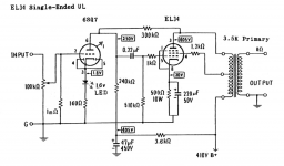
This is an SE amp I designed to use the very linear 6SQ7 high gain tube as a driver, built with some Edcor 15W 3.5k OT, to a UL tapped EL34. This amp sounds fantastic and is a simple/cheap design to build. It drives to full power without a pre-amp, which works great with my EAR 834 clone phono stage or straight from a CD deck.
I've tried a variety of 6CA7, KT77 etc. and settled on a pair of JJ EL34 tubes. I played around with various cathode bias schemes (I had no interest in a grid leak bias design I saw some circuits use with this tube), and the combo of a LED + resistor, and tying the diodes to the cathode, sounded the best. Like my other amps, it uses plate to plate Schade feedback and any UL tapped OT from 3.5K to 5K should work fine.
In the future I plan to do another video series on building this amp, but given I found very few designs online for the 6SQ7 tube used for hifi, I thought I'd go ahead and share this.
Attachments
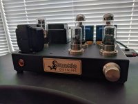
stephe, that's a very nice build there. I wish my work looked that nice. I'm such a klutz when it comes to metalwork and that kind of thing.
6A3sUMMER, while it is definitely true that 6SQ7 characteristics are similar to 12AX7, I think dgta's question was a good one. I looked up 6SQ7 data and saw that its rp is really high:
For 6SQ7 with Vp = 250V and Ip = 1.1mA, rp = 85k ohms. (gm = 1.2mA/V)
For 12AX7 with Vp = 200V and Ip = 1.2mA, rp is 62k ohms. (gm = 1.6mA/V)
Would an additional 20k ohms of rp make a big difference to the local NFB loop from the output tube plate to the driver tube plate? Or is that too small to make a meaningful difference? It would be kinda nice to be able to build a good-sounding amp with garden variety guitar amp toobz like 12AX7 and EL34...
-
dgta,
The 6SQ7 Triode is close to a single triode of a 12AX7.
But Octal tubes are nice!
The octal tube closest to the 12AX7 mu/gm/rp is 6SF5. A fine tube with nice curves.
rongon,
and
dgta,
Try and run a 12AX7 triode at 250V and 1.1mA,
instead of at 200V and 1.2mA.
You will find the following:
At that operating point . . .
the bias voltage has to be increased, (grid more negative versus the cathode) so:
rp increases
and
transconductance decreases.
Hmm, the 12AX7 at 250V and 1.1mA is beginning to act real close to the 6SQ7 specs.
Remember, tube manual specs have some suggested examples of quiescent operating conditions, but they do not tell the whole story.
Do not limit the only conditions to the few tube manual specs, look at the tube curves and see what else may be a better operating point to get the rp, and Gm that you want.
and
dgta,
Try and run a 12AX7 triode at 250V and 1.1mA,
instead of at 200V and 1.2mA.
You will find the following:
At that operating point . . .
the bias voltage has to be increased, (grid more negative versus the cathode) so:
rp increases
and
transconductance decreases.
Hmm, the 12AX7 at 250V and 1.1mA is beginning to act real close to the 6SQ7 specs.
Remember, tube manual specs have some suggested examples of quiescent operating conditions, but they do not tell the whole story.
Do not limit the only conditions to the few tube manual specs, look at the tube curves and see what else may be a better operating point to get the rp, and Gm that you want.
Last edited:
Ummm... not quite. 6SQ7 has rp=110k at 100V and 0.5mA, Vg=-1. 12AX7 has rp=80k at the same exact operating point. That's a substantial difference.
Yes, you should look for the most desirable operating point of the tube you choose. But some tubes can have characteristics not attainable in other tubes")
Yes, you should look for the most desirable operating point of the tube you choose. But some tubes can have characteristics not attainable in other tubes
A good case can be made that the Gm of the driving triode is the significant bit. Its loading impedance is a parallel of its plate resistor, the output valve's grid resistor, Miller and stray capacitance, and most significantly, the summing node impedance from the feedback resistor. This is the value of the resistor divided by the gain of the final stage plus one, just like Miller capacitance.
So, if final stage gain is, say, 9, then the driving triode has to drive 300K / (9 + 1) = 30K Ohms, in parallel with all the easily visible loads.
Not an ideal load for a high mu triode, and why this topo is not optimal. More interesting is why this topo is successful and popular. My personal, off the cuff, theory is that simplicity gives robustness in real world implementations. Everybody, commercial and DIY, cheats about RFI filtering, power supply damping, grid and cathode stops, Zobels, etc. etc. and the less complexity the more latitude to cheat on best practices. Changes in latitudes, changes in attitudes.
All good fortune,
Chris
dgta,
You are correct, 6SQ7 rp 110k, 100Vp-k, Vg -1, and what you did not mention . . . only 0.5mA.
But. . .
The schematic on Post #1, shows a quiescent operating point that is very far removed from that.
6SQ7, 1.8V bias, 0.2V across 160 Ohms, 1.2 mA.
Under those conditions, the 6SQ7 rp will be less than 110k Ohms.
(Look at the triode curve slopes that are Less steep at 0.5 mA, versus the Steeper slope at 1.2mA).
I hate acronyms, but here comes one from me . . . IRMC
Just saying.
Last edited:
dgta,
6SQ7, 1.8V bias, 0.2V across 160 Ohms, 1.2 mA.
I do want to add, those voltages listed are approximate to help someone building this amp ensure they are in the ballpark. The LED may have been 1.67V ish, it's been a while since I built this. I tried it with a lower V drop LED and to me this red LED sounded better than the lower 1.2Vish voltage drop infrared one. And that could just be the LED type itself, not the actual voltage drop.
And I might be way off here, but wouldn't the more accurate measurement of the current across the tube be the voltage drop across the plate load resistor? 155V across 240K at idle?
And I don't doubt I could have build this with one small 12AX7 driving these two EL34 tubes and playing around with component values, ended up with a nice sounding amp. I just wanted a high gain octal single triode, ran across the data sheet for these, which BTW has a nice chart about how to get different amplification factors out of it.
I do like using oddball tubes when possible. Being able to use these mostly forgotten tubes, with a Navy Anchor on them, was a bonus
Carry on, I just wanted to clear up that these voltages weren't posted to any decimal point perfection, I never sim'd this design (honestly I would have no idea how to) and ended up where I did mostly by trial and error, listening and changing things until it sounded good to me.
stephe,
Thanks for your continuing comments!
And, it should be noted that the plate current of the 6SQ7 is coming from both the 240k plate load resistor, and from the 300k Schade feedback resistor.
As to exact voltages and currents, take a bin of tubes, and they may easily be 5% different in their exact rp, Gm, and plate to cathode voltage, and current.
My power mains voltage varies from 117V to 123V, centered on 120V.
100 x (3V/120) = 2.5%
So, my B+ varies by +2.5% to - 2.5% (5% differential).
And the filament voltage also varies that much too.
A Positive item:
So many of you builders have got me interested in using Octal tubes for the input tube. They look great!
Last edited:
stephe,
Thanks for your continuing comments
A Positive item:
So many of you builders have got me interested in using Octal tubes for the input tube. They look great!
Thanks for the reminder about the feedback resistor and yeah, a lot of the build for me is the appearance. I also think I have a different approach to building amps than some folks, I'm not afraid to play around with resistor values and voltages, and then listen to how that changes them. Especially when you are using low $ tubes, worst case is you kill it lol.
The octal tube closest to the 12AX7 mu/gm/rp is 6SF5. A fine tube with nice curves.
Take a look at the 6SQ7 curves vs the 6SF5. The 6SQ7 is a very linear tube and probably contributes to the great sound this amp produces.
Yes, but you should then remove, or at least raise the value of, the plate to plate feedback resistor, as a triode strapped output tube really doesn't need that much feedback and will help get back some of the power lost going to a triode mode setup. You can try raising the value of that resistor to 500-800k (or even remove it entirely) and adjust the amount of feedback "to taste". It does have a pretty substantial impact on the tone of the amp.
I assume you're aware that you'll lose a lot of power in triode. Output power will probably be half, or even less than half, of what you get in UL.Stephe, can I use it in pseudo triode configuration instead of ultralinear since I don't have a transformer with ul socket? Do I need to change any values? My OT is ISO FC 12S. I'm newby, sorry for the trivial question
Another, much simpler, option would be running it in pentode mode instead of UL.
Just run power to the screen (G2) from B+ and increase the value of the G2 resistor so you get the same voltage as you would with UL. The operating point of the tube will be the same. The rest of the circuit can probably be left unchanged.
I assume you're aware that you'll lose a lot of power in triode. Output power will probably be half, or even less than half, of what you get in UL.
Another, much simpler, option would be running it in pentode mode instead of UL.
Just run power to the screen (G2) from B+ and increase the value of the G2 resistor so you get the same voltage as you would with UL. The operating point of the tube will be the same. The rest of the circuit can probably be left unchanged.
Might need to toy around with the plate to plate feedback resistor a bit, I'd start with the 300K and also try various values down to 180K. Too high and it will be overly bright sounding, too low and it will sound muffled.
- Home
- Amplifiers
- Tubes / Valves
- 6SQ7 - EL34 SE amp design