So, after using this amplifier nearly all day, every day, it still continues to deliver the goods. I've been considering building a couple more on request of a few family members and friends, but, that gets a little tedious. So...
Would there be any interest in PCBs for this project? I think it would be a fantastic first project, and a great affordable way to go for low power speakers, or even headphone use. If I end up building a few more of these, I sure would love to do it on PCBs.
If so, I might be interested in having some made, and making them as user friendly as possible. Especially after building a few versions of the power supply for a few other projects, I think it would be pretty useful. So far, I've thought of the following features/changes-
Complete amplifier all on a single PCB, including PSU stage, since it's so simple. Likely shooting for a 100mm X 150mm size factor if possible.
Mosfet at edge of board for easy attachment to chassis, options for either simple resistor divider for gate, or Zener stack, possible trim pot for fine adjustment for the anal types. UF4007 type discrete diodes, or bridge. Can also be easily bypassed for outboard PSU options (tube rectifier, chokes, etc)
Screw terminal spacing for off-board connections to transformers
Parts outlines with multiple holes to accommodate different parts types (especially for capacitor sizes)
Garter bias for output tubes, with additional holes for different bias options via jumpers (traditional cathode bias, outboard CCS modules for differential amplifier configuration, etc) in theory this would even make the amp board suitable for driving big boy tubes if one were to use traditional plate loads for the outputs...
Additional holes for alternative wiring of phase splitter arrangement, such as floating/self biased concertina, additional holes to allow partial bypass of cathode resistor, or use of LED for bias, with feedback resistor underneath
Filament wiring would be run directly to the PCB, but there would be holes to allow jumpers for DC operation for those that would like it, or for use with an SMPS type of main supply voltage, off of a basic 12 volt supply. Might be a good option.
Also, I'm considering making the boards use noval/nine pin input/splitter tubes, for better versatility with current production tubes. This would mean that the 6DJ8, 6N1P, 6N2P, 6CG7/6FQ7 and even 12AT7/12AX7 types could be used. This would be even better for beginners that like to "use what they have" I would think. I still like the all octal version, and might do both if there is interest. I don't think there are too many options for noval outputs, other than 6CG7, 6FQ7, 6N6P, or (shudder) 12AU7, so unless there is interest in a bunch, it's likely staying as 6SN7 octal for the outputs. Then you have the option of running the cathode resistors off board, and running something goofy like the 6AS7, if one were so inclined, although it would be a tight fit!
Any comments? I've been playing with easyEDA lately and think that I want a few boards either way, I would just love some input from anybody that might be interested, or would like to lend a hand at the PCB side of things. Anybody that wants to help may get a board or two for their troubles!
Lingwendil, I've been plotting a build of this thing for a while now. I'd had similar ideas on and off for years, but you've actually completed one and I'm going to build a copy. Thank you, BTW.
My years as a tube amp repair tech are LONG behind me, so I don't have the collection of parts to just whip one up. I've acquired an enclosure, the toroids, and any passives I didn't have on hand... but still haven't pulled the trigger on the sockets or tubes. I thought about a terminal strip and air circuits, but as I design PCBs for a living I'm probably going to rip a quick one out for this amp. It'll be a nice change of pace from BGAs and DDR3 busses, and a different set of PCB design rules. I'll send you one after I build it and make sure it doesn't smoke; not front-burner, could be a while.
I like the way you're thinking with alternate configurations, etc. That sounds like a more universally-interesting board than the one I plan to fab.
Thanks again for the design and the inspiration.
Count me in for 1 board.
Stay with octal. There are other nine pin alternatives available.
Thumbs up for proposed pcb source.
Stay with octal. There are other nine pin alternatives available.
Thumbs up for proposed pcb source.
Any ideas on affordable output transformers other than toroids? I'm trying to get a BOM together and want some alternatives listed. Seems like an 8k or 10k with a 8 ohm load on a 4 ohm secondary will put us in the right ballpark for impedance, but the only affordable EI cores i see are the Edcor units, and international shipping might be too much for some folks on those. Hammonds look too pricy for such a project too.
I may be interested, in part depending on cost (my audio budget is pretty limited) and in part how it is laid out. In particular if I could use it for 6AS7 per earlier discussion (still haven't started that project other than to gather the parts from my parts bin and order some iron).
What's wrong with toroids? Flat response from 10Hz to 100KHz is not enough?
Not everyone wants to use toroids, from some of the questions and suggestions I've had from others. Just wanted to have more options for people.
I may be interested, in part depending on cost (my audio budget is pretty limited) and in part how it is laid out. In particular if I could use it for 6AS7 per earlier discussion (still haven't started that project other than to gather the parts from my parts bin and order some iron).
It would be easy to run wire to off board components for that use. I've got that in mind too.
Depends on options, board size, and how many people I have interested, really. Once I get something drawn up in easyEDA I'll post it up for comments. So far I've just got some paper sketches of layout that I'm using for mockup. There do seem to be a handful of pretty affordable board houses if I keep the board of a reasonable size, tentatively I'm thinking of shooting for something in the 100mm X 150mm form factor.If it's up to me I think that $15USD each is about the most I want the finished cost to be, that way shipping doesn't crank it up too high.
I'm off work tommorrow, so I might try and work on a layout tonight if I have time, but I currently have an EL86 stereo PP taking up the kitchen table that needs to be finished up first 🙂
I'm off work tommorrow, so I might try and work on a layout tonight if I have time, but I currently have an EL86 stereo PP taking up the kitchen table that needs to be finished up first 🙂
In the ballpark of $15 I’m definitely in - maybe even two!
1.2w is perfect for my hi freq multicell horns 😱
1.2w is perfect for my hi freq multicell horns 😱
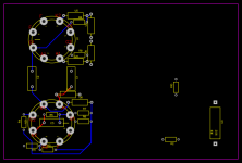
Using EasyEda to start a crude PCB design, keep in mind I am not very good at this, so any suggestions are welcome. Mainly using EasyEDA since I can work from work and home, and it's pretty easy to use. SUGGESTIONS ARE WELCOME!!!!! This is very early stages, so don't laugh 🙂
Blue is bottom traces, red is top, pretty simple. Still need to add the output cathode bypasses, and the front end plate resistor. Once one channel is good I'll copy everything over to the other side. Ignore the random parts on the right side of the pic for now. The plan is to run twisted pair wiring straight to additional pads near the heater pins to allow trouble free AC heating, and I may add jumper positions to allow the use of series connection from 12 volts if there is room after everything else.
Need to figure out how to copy the silk layer on top to the bottom, and once I get everything more or less how I like it (and acceptable for everyone) I'll worry about going thicker on traces, enlarging copper areas, and maybe adding additional pads/holes for accommodating different components. Once that's all done I'll figure out if we can fit the mosfet PSU in the center of the board, but that's not a primary concern, I'll mess with that once the main circuit is good. So far it looks like it can fit though...
Attachments
Once I get a finalised board design together I'll start formally taking down counts. I'm not the most organised guy, so it'll be easier to keep track at that point.
- Home
- Amplifiers
- Tubes / Valves
- 6SN7 push pull flea amplifier project