I can attest that garter bias is a great system for biasing up an amp like this. I build a PL82 PP amp with garter bias and it sounds great.
However 6AS7 project its going to be very wasteful. I suggest digging into the Tubecad articles a bit deeper because he showed another garter bias arrangement which used transistors which saved a lot on the voltage overhead. I built a 5687 preamp with wilson current mirrors for equal bias on both sides, and the tubcad article I mentioned is a hybrid of pure garter and current mirror.
Shoog
Here is the only article on garter bias and it covers the transistor variant.
Blumlein’s Garter Circuit Revisited
What power do you get out of your 5687 flea.
Shoog
Blumlein’s Garter Circuit Revisited
What power do you get out of your 5687 flea.
Shoog
Only article eh 😛
Amplifier auto bias circuits: Alan Dower Blumlein's garter circuit
Interestingly, I can't find much reference to garter bias, other than mentions that he wasn't the first to do it, I have a similar patent printed out somewhere but forget the number and author. The patented version has additional components however, so is not exactly similar.
EDIT- Murray John Somerset
Patent US3127569 - Valve amplifier push-pull output stage - Google Patents
Last edited:
Here is the only article on garter bias and it covers the transistor variant.
Blumlein’s Garter Circuit Revisited
What power do you get out of your 5687 flea.
Shoog
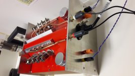
Very little. Less than 1watt. That was another one of those 'use the parts in the bin' project and the b+ is a lousy 200volts. I have also built this pse with 3 5687 and one 6922 per ch.
Attachments
😱
That's effin' rad dude! Gives me ideas for parallel push pull designs now! Six bottles per side for a fancy V12 amp with something like EL84 or 6V6 would be sweet, and I just so happen to have a dozen of each on hand if I'm not mistaken...
Got a schematic?
Bidding on some tubes on eBay to hopefully get a few pairs of some GTA types for the higher voltage version of this flea design, maybe even some goofy coin-base tubes...
Last edited:
Thanks. My next engine will use tubes with top cap. I also have drawn up a 45degree V2 with 813s. Harley music engine.
For anybody wondering, this would make a killer headphone amplifier, especially for power hungry 16-32 ohm headphones...
You got me pegged 😉 I recently designed a little differential headphone amp (5687 or ECC99 output tubes) but I've wondered about how a 6SN7 might behave in a similar arrangement. The issue was finding a transformer that will keep them happy (pretty high turns ratio needed for the 6k Rp).
Grab a transformer that you would usually use for an EL84 or 6V6 (from 8k~10k) push-pull, and run twice the nominal load impedance on the taps (examples- 8 ohms on a 4 ohm tap, 16 ohms on an 8 ohm tap, 32 ohms on an 8 ohm tap) to give anywhere from 16-20k load, and it should work well. For such low power 70 volt PA line transformers work well too, as long as they have the correct taps. I have a few line trannies from Atlas Sound that work great for this purpose. Or, be a loon like Shoog and me and play with power toroids 😉
Yeah, after responding I realized that 8k:4 ohm would actually be about right for 6SN7 push pull. The ECC99/5687 amp I mentioned used an 8k:8 ohm Edcor for 8k per tube with a 32 ohm headphone load. Too bad most Edcors don't have the multiple taps.
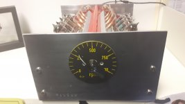
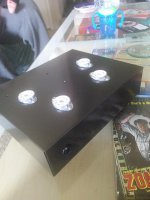
Got a few holes drilled, then had to do daddy stuff. Got a 9 volt on the power LED just to get myself some hype for the build. Should look nice once it's painted black.
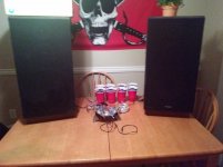
After the kids went to bed I dug out and hooked up the big Fisher 825 cabs for some more listening tests. This thing makes BASS! Most music sounds good in general, but anything with lots of synthesized sound is phenomenal, Depeche Mode in particular! I can't wait to get this thing finished up in the chassis, and start on another one for the garage.
After the kids went to bed I dug out and hooked up the big Fisher 825 cabs for some more listening tests. This thing makes BASS! Most music sounds good in general, but anything with lots of synthesized sound is phenomenal, Depeche Mode in particular! I can't wait to get this thing finished up in the chassis, and start on another one for the garage.
Attachments

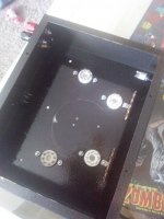
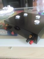
Got it painted with some rustoleum hammered paint, this stuff is nice for hiding imperfections and scrapes, highly recommended. Also got the jacks and power switch in. I went with a center layout for the power transformer, otherwise the front of the amp would be cramped with all the sockets, and I wanted a wider layout. Hum shouldn't be an issue at such low current judging by past experience.
Now I just have to bolt down the transformers and start final construction!
Now I just have to bolt down the transformers and start final construction!
Attachments
Not yet. I had one wired up spaghetti style for a week or so running daily that worked rather well, but the final product is not complete just yet. Still have to finish the PSU wiring and the cathodes of the outputs, just not enough time in the day (I work graveyard mostly, and six or seven days a week often) so it's on the back burner behind everything else. The transformers, sockets, plugs, etc. are all mounted and the majority of the build is finished otherwise.
On a bright note though, I sourced some nice NOS 12SN7 and 12SL7 tubes to set aside for another version at some point. I would love some coin-base tubes for the look, but they keep selling higher than I'm willing to pay 😀
On a bright note though, I sourced some nice NOS 12SN7 and 12SL7 tubes to set aside for another version at some point. I would love some coin-base tubes for the look, but they keep selling higher than I'm willing to pay 😀
I'm curious because I just was given a box with some random tubes and 6SN7 and 6SL7s were in the box.
My brain is telling me to do something quick and cheap with them. I found your thread and you have me hooked!
My brain is telling me to do something quick and cheap with them. I found your thread and you have me hooked!
So, I've been so busy that this thing was sitting half finished for a good long while. We moved recently, and I just dug it out to finish it up. Just need to wire up the filaments, power jack and switch, and a few little things, and now I'm second guessing my power supply. I was originally going to do a CRCRCRC type of filter, but might go for a mosfet capacitance multiplier instead. Any thoughts? I'm thinking that an IRF820 and a single preceding CRC would be plenty, and drop less voltage.
Also in the works is a big parallel version of this guy, with source followers and fixed bias for AB2 with 6SN7GTA/B types. Stay tuned...
Also in the works is a big parallel version of this guy, with source followers and fixed bias for AB2 with 6SN7GTA/B types. Stay tuned...
CRCRCRCRC? For reasons that are harder to explain than I care to go into, the real "win" is to use active regulation, in 2 stages. Its the cure that solves a half-dozen shortcomings.
rectification
→ C
→ → R
→ → → C
→ → → → series reg Nº 1
→ → → → → C
→ → → → → → R (small)
→ → → → → → → series reg Nº 2
→ → → → → → → → C
Each regulator, even if as simple as a bipolar emitter follower (darlington config), gains you about –40 dB ripple reduction or better. I use high gain darlingtons, so I get about –55 dB/stage. 2 stages obviously is –80 to –100 dB or so. Quiet as a mouse.
You get the added benefit (if you use Zener HV voltage references) of having a PS that becomes independent of domestic power line surges and fluctuations. It becomes “portable” to friends' houses for demonstration or evaluation. It also costs near-nothing to implement.
It may be my personal electronic-design jïhad, but I really feel that too much is made over various passive power supply filtering topologies (excluding regulation). Regulation isn't entirely a cure-all, but with good-sized 'output reservoirs', the instantaneous power supply impedance is surprisingly low. mΩ.
GoatGuy
I was even thinking a stack of zeners feeding a source follower would be a good solution (a ccs fed stack of VR tubes would be fun if I had the chassis space 😀) but for this I think absolute regulation isn't as important as just a quiet supply. What I'm thinking of doing is a CRC, then a Mosfet with a filtered gate voltage, then another small film cap CRC feeding the input/phase splitter. Something like this-

Of course the values are off the top of my head, but you get the idea.
Maybe even a tiny choke? I think I'm only pulling around 50mA idle altogether so maybe a tiny PC mount choke or two would work?
I'm not married to doing it passive at all, I'm just trying to figure out an elegant and compact way to do it that doesn't involve a huge mess of caps lol
Yeps. It will work. I personally like the “light show” of VR tubes, but I like the zero-volt strike voltage of a string of 2 watt, 37¢/ea Zeners. There's no reason not to do both, as no one actually would know whether the VR tubes are just light show or actually 'working the gig'.
I like hi-volt emitter followers because I have come to distrust MOSFETs in hi-volt applications where startup volts can be quite different from quiescent. BJTs are just reliable. Their BASE pins do reasonable things with over-volt transients. JFETs too, tho' you can't get them in silicon in hi-volt configurations. Silicon carbide? Sure. 1000+ volts. But they don't cost $1 buck or so apiece.
There are also plenty of more complicated (and de-complicated PCBoard kits) designs too. Ones that actively regulate their output and have 'error amplifiers' to squash even teeny-tiny variations. And lower output impedance without the caps. I still like caps tho: puts less urgency on the regulator piece. KISS - Keep it Simple, Silly! is a great thing to remember when designing.
Your design is fine, too: but it isn't (in the configuration shown) going to do as much ripple reduction as you might like. You should drop voltage by a larger degree … to have more ripple margin. Takes an extra resistor to make a quick-n-dirty sub-voltage reference. The 1,000 R that you spec maybe ought to be larger. Maybe not. If making a sub-volt 'floating reference' (instead of Zener clamped), just use a 1:40 resistor ratio. RTOP = 12 kΩ, RBOT = 470 kΩ. Same capacitor.
300 V in (say) * 470 / (12 + 470) = 288 volts. 7.5 volt ripple margin
PS: if you like MOSFETS and trust 'em, then by all means, use 'em. My fears are old, as I am old. Having shît blow up is kind of a remember-for-lifetime event. But as I say… I'm old, and in the 'not-so-good Old days', MOSFETs were nowhere near as robust as they are said to be today.
GoatGuy
Last edited:
(This is exactly the sort of discussion I was hoping for! Thanks!)
So, looking at all of that, it's all looking pretty good. Funny enough one of my other considerations for a power supply for this originally was going to use the Maida regulator that Sy used in the Red Light District, but with the transformer only giving ~305 volts rectified I didn't want to drop the ~20 or so volts I like to see in a Maida, but it looks like a target of 285 volts clean for the preamp makes the most sense.
Looking through my parts last night I found a handful of TIP50 that I suppose I could use, but funny enough I have had better luck with mosfets in the past, so overlooked them. Since we are only pushing ~50mA at idle I don't think there would be that big of a difference between a bipolar or a fet here. I suppose we could feed the TIP50 with a 12k/470k divider and see how it does for this. Otherwise I have the IRF820 on hand too.
Back to the Zener idea however, would it make a big difference in ripple using a stack of Zeners close to 285~290 volts instead of the 470k? This should give a more solid reference and be a bit more immune to ripple, and won't take up all that much room anyway. I know higher voltage Zeners can be noisy, but how many Zeners should I be looking at using here? 4~5? 10? I don't have any on hand so I would need to order some anyway.
Would we even need the CRC after the output of the "regulator" anyway? I'm thinking a small (5-6u) film cap should be plenty there. I have a bunch of 4, 5, and 6u film caps I could throw there.
- Home
- Amplifiers
- Tubes / Valves
- 6SN7 push pull flea amplifier project