Sounds like fun! Shoog has done a lot with the 6AS7 too, and done some neat tricks with CCS tails for differential operation. Those transformers would work well with the secondaries in series. Might be fun to play with balanced feedback with some sort of differential driver stage if you ground the center point of the series connected secondaries and run ± feedback across the speaker terminals...
I've got a pair of 6336A that would be perfect for such a build, I've had them for years and never used them...
I've got a pair of 6336A that would be perfect for such a build, I've had them for years and never used them...
Sure, wouldn't mind at all, but some quick facts for my experiences and application (posted here so others can benefit) <snip>
Well, this is helpful indeed. The 60-65v PP confused me as I thought these tubes always needed 100-200vPP. And that's why I wondered about your operating point and cathode resistor values. I'll look at the curves and see. In any case, I was looking for 100mA or so and lower B+ as you've done along with garter bias for just the purpose you mention, with roughly 8w out, so your project is pretty spot on what I was thinking. Except the driver requirements may be a bit simpler than I thought. BTW, what kind of phase splitter did you use? I was thinking about a transformer based splitter ala Shoog's efforts.
Anyway, thanks again and sorry for the interruption.
No apologies needed 😉
The exact same front end that I posted on the first page of this thread is what I used, it's my go-to phase splitter arrangement, because I have a perverse love affair with the 6SL7
The 6N2P or 12AT7 would also work well for the same circuit, with adjustment of a few parts values. You want to be a real Cool Kid™? Add a CCS load on the plate, and use a pentode as the voltage amp, and a 6DJ8 or a mosfet for the concertina section 😎
Depending on your source you may not have enough gain to use it as-is though, it all depends. I ran it without feedback with the 6AS7, but if you have extra gain adding a little negative feedback wouldn't hurt, try it and see. I like adding feedback when I can.
The juice was definitely worth the squeeze!
So, for anybody that cares, some updates. I've been running this practically non-stop daily at home, and it's running off of our entertainment center as the only sound output. Not only has it gained the extremely rare approval from She That Raises My Kids ( 🙂 ) but it has easily become my favorite build of all the projects I've done so far. I built a bigger set of Karlsonator speakers using two 3FE25-16 per channel (wired in parallel for 8 ohm load) that have even higher sensitivity (97dB/1w!) and overall quality. This amplifier and the K's are a match made in heaven for overall listening, and what I will in all seriousness call theatre quality imaging.
Anybody that has seen my posts will know that I shy away from audiophile terms and snake oil types of dealings, but I can easily say that this amplifier and speaker combo is magical, definitely worth the time to build. I ran it with the negative feedback disconnected for a couple weeks, and have since hooked it back up. For what it's worth, the TC9 Karlsonator speakers sounded nearly the same with or without it, but the 3FE25 Karlsonators definitely work much better with a bit of feedback. The bass is more "clean" sounding, and I'll potentially draw some scorn by saying that the feedback definitely improves the imaging and dynamics of the combo. It's a noticeable improvement all around with GNFB, but it's not objectionable without it. I'm still using the 2.7k/27k cathode resistor/feedback resistor combo. It sounds so good that I'm leaving it that way.
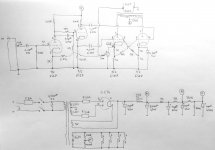
Minor changes to the schematic as well. The input stage (attached) now has my now customary concertina splitter arrangement, that uses the divided down DC bias voltage, with AC shunted to the grid. It works fantastic, and I highly recommend you try it.
The mosfet filter works amazingly well. Pressing your ear against the speakers' cone at zero signal is absolutely silent, no hum, ripple, or hiss, unless it's coming from your source. Not bad for a couple buck's worth of parts! Total amplifier draw is 41mA, and both input/PI and output stage are running through the mosfet, and I'm dropping 305 volts down to 284, with 6~ volts through the RC preceding the mosfet. A small heatsink on the mosfet keeps it barely warm, just to be safe, as it's dissipation is just over half a watt. With as well as this PSU works, I'll never buy a filter choke again.
Quick and dirty multimeter-across-the-speaker-terminals show that 2.3VRMS (~1.3W/8ohms) is where the amplifier starts to sound just a hair funky, but that's way, way, higher than comfortable listening volume. Average level for our usual use shows about 300~500mVRMS. I'll safely say that this is a "1 Watt" amplifier, and it punches far beyond its weight.
I like it so much I might dig out my stash of clear-top 6CG7 tubes and build a noval version with the 6N2P-EV as the input tube 😎
I'm currently running a NOS pair of yellow ink "chrome-dome" Westinghouse 6SN7GTB in it (hey, they were cheap, and have high WAF) with the Russian 6H9C 6SL7 equivalents up front, for anybody who may ask.
Please, please, someone else build one of these! I can't emphasize enough how good this little amplifier is. If I had the time and patience I would draw up a nicer schematic diagram and try to get PCBs made. This would be a killer beginner's first build if nice PCBs were available, and very affordable.
So, for anybody that cares, some updates. I've been running this practically non-stop daily at home, and it's running off of our entertainment center as the only sound output. Not only has it gained the extremely rare approval from She That Raises My Kids ( 🙂 ) but it has easily become my favorite build of all the projects I've done so far. I built a bigger set of Karlsonator speakers using two 3FE25-16 per channel (wired in parallel for 8 ohm load) that have even higher sensitivity (97dB/1w!) and overall quality. This amplifier and the K's are a match made in heaven for overall listening, and what I will in all seriousness call theatre quality imaging.
Anybody that has seen my posts will know that I shy away from audiophile terms and snake oil types of dealings, but I can easily say that this amplifier and speaker combo is magical, definitely worth the time to build. I ran it with the negative feedback disconnected for a couple weeks, and have since hooked it back up. For what it's worth, the TC9 Karlsonator speakers sounded nearly the same with or without it, but the 3FE25 Karlsonators definitely work much better with a bit of feedback. The bass is more "clean" sounding, and I'll potentially draw some scorn by saying that the feedback definitely improves the imaging and dynamics of the combo. It's a noticeable improvement all around with GNFB, but it's not objectionable without it. I'm still using the 2.7k/27k cathode resistor/feedback resistor combo. It sounds so good that I'm leaving it that way.
Minor changes to the schematic as well. The input stage (attached) now has my now customary concertina splitter arrangement, that uses the divided down DC bias voltage, with AC shunted to the grid. It works fantastic, and I highly recommend you try it.
The mosfet filter works amazingly well. Pressing your ear against the speakers' cone at zero signal is absolutely silent, no hum, ripple, or hiss, unless it's coming from your source. Not bad for a couple buck's worth of parts! Total amplifier draw is 41mA, and both input/PI and output stage are running through the mosfet, and I'm dropping 305 volts down to 284, with 6~ volts through the RC preceding the mosfet. A small heatsink on the mosfet keeps it barely warm, just to be safe, as it's dissipation is just over half a watt. With as well as this PSU works, I'll never buy a filter choke again.
Quick and dirty multimeter-across-the-speaker-terminals show that 2.3VRMS (~1.3W/8ohms) is where the amplifier starts to sound just a hair funky, but that's way, way, higher than comfortable listening volume. Average level for our usual use shows about 300~500mVRMS. I'll safely say that this is a "1 Watt" amplifier, and it punches far beyond its weight.
I like it so much I might dig out my stash of clear-top 6CG7 tubes and build a noval version with the 6N2P-EV as the input tube 😎
I'm currently running a NOS pair of yellow ink "chrome-dome" Westinghouse 6SN7GTB in it (hey, they were cheap, and have high WAF) with the Russian 6H9C 6SL7 equivalents up front, for anybody who may ask.
Please, please, someone else build one of these! I can't emphasize enough how good this little amplifier is. If I had the time and patience I would draw up a nicer schematic diagram and try to get PCBs made. This would be a killer beginner's first build if nice PCBs were available, and very affordable.
Attachments
Well, it's tempting. But I have to finish my 6AS7 first. I'm thinking of a different front end and it'll be the first time I try to design something like that from scratch. So I'm moving slowly...
But when I'm done with that maybe I'll give it the 6SN7 a try. I have a few lying around with no plans for their use yet.
But when I'm done with that maybe I'll give it the 6SN7 a try. I have a few lying around with no plans for their use yet.
As soon as I can get a good deal on eight of the same date code of some older 6SN7GTA/B I'm doing a parallel version of this guy, and possibly go higher supply voltage for more oomph. might even feed the grids with mosfet followers to go AB2 
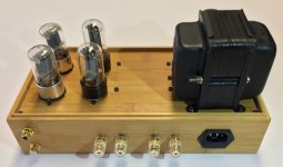
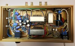
This is my version of the Lingwendil amplifier, with tube power supply. It works well, no hum and good stability. It is one of my best sounding small amplifiers: post #65 is not an exageration. Beside the power supply, the only difference from the original schematic is the value of the cathode resistor on the first 6SL7. I used 3K instead of 2k7, because this is the same resistor value I used on the power supply section.
It has been a no-cost weekend build, with parts I already had. The chassis is a repurposed Zeller 13333 box from Amazon (30x15x7cm), it is cheap and easy to drill. Heat dissipation is poor, but this is definitely not a issue here. I also needed a comparatively high chassis to squeeze the tubes in a small place, because this way I was able to arrange some resistors in a vertical fashion under the sockets. The power transformer and the filter choke are from a late '40 tube radio. I never used iron so old on my builds before, due to safety concerns, but this transformer was in great conditions and the total current drain is so low that it remains cold, so a paper insulation breakdown is unlikely. Of course it has been througly checked, repainted, opened, and all the failing rubber wires have been replaced. I like parts that looks old, and this one surely is.
Output transformers had come out from a late '60 Saba radio with push-pull ECLL800 output tubes. They are rated 11K primary to 4 ohm secondary, 8W. The primary is split on two (maybe four) sections, and there is an auxiliary feedback winding that I left unconnected. My speakers are rated 6 ohms so the reflected impedence is in the ballpark of the design. Ceramic tube sockets are reclaimed from old equipment. I was about to use new cheap chinese sockets, but after a ultrasonic cleaning bath with soapy water the old sockets came out as good as new, and they are far better. I had a 10K RK27 Alps volume potentimeter in the drawer so I used it; I would have rather bought a 100K one. All other components are new, the values are so common that I had plenty of them on my drawers. I used Nichicon and Vishay capacitors.
The build was easy and component placement straightforward. I rotated the socket key of the output tubes 90 degrees relative to input tubes, this way the coupling capacitors have a parallel arrangement. Looking back at other builds with unconventional designs, I put the finished but never turned on amplifier on a shelf for a few days, in preparation for a long fault-finding session. Well, the Lingwendil statement at post #18 is true: I turned on the amplifier ...and it worked. No oscillations. No hum. All the voltages are spot-on. Nothing else to do, just connect the good speakers and listen to music. I haven't been able to test this amplifier on high-end speakers, but it looks promising. Compared to other small amplifier with global feedback I have, it sounds better (to me) than a Mullard three-watt clone with ECL86 and pretty good output transformers. It even drives comparatively inefficient Q-acoustic 3020 speakers plus passive sub (8 inch driver) at the standard volume I'm used to listen. Low frequencies are reproduced just fine.
A big thank you to Lingwendil for this successful new twist to the PP 6SN7 / 6SL7 small amplifier design.
Attachments

Last edited:

Beautiful build! It looks very nice, and great use of reclaimed vintage iron! I can't stop telling people about this build, it's a heavy hitter quality wise for sure. I'm going to build a noval version eventually with 6CG7 outputs, since I've got a bunch on hand.
Output power isn't much, 1.3w max, but it sure is worth it. Ours is turned on literally all day cranking either tunes or for tv/movies.
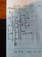
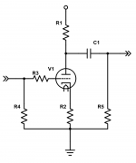
Minor observation, on your schematic, did you omit the 1M resistor from the concertina splitter grid to ground? It will work without it, but will work better with it in place.
Output power isn't much, 1.3w max, but it sure is worth it. Ours is turned on literally all day cranking either tunes or for tv/movies.
Minor observation, on your schematic, did you omit the 1M resistor from the concertina splitter grid to ground? It will work without it, but will work better with it in place.
My bad, it was a drawing error, I re-uploaded the correct schematic. Your design really surpassed my expectations. By the way, what is the purpose of the parallel between 1M resistor and 100nF capacitor on the coupling between the plate of the first stage and the splitter grid? I haven't seen this arrangement on other amplifiers of this type.
Splits the DC voltage in half, and sends signal straight to the grid full strength, it lets you bias half the supply voltage across the splitter tube for maximum headroom
That's a clever trick. The only minor inconvenience I've found is that when I connect low voltage sources such as smartphones, I need to turn the volume control near to maximum. On other amplifiers, I installed a 1:4 step-up transformer right at the input, before the volume potentiometer. This is the purpose of the spare lug I left for future use near the input side of the amplifier. But the volume is still enough and I never had to turn the knob to full stop.
I've found that on my system and for my musical choice 0.5W per channel is enough, so I am currently experimenting with low-power amplifiers to get nice sound at a significantly lower price than conventional solutions. The other minor issue is that the overall size of the amplifier is basically the same of a much more powerful one. I've chosen the smallest possible chassis for this build, and still is twice as big as other small power amplifiers I have. The 6cg7 seems to be a really good idea, by the way I have several of them on my drawer...
I've found that on my system and for my musical choice 0.5W per channel is enough, so I am currently experimenting with low-power amplifiers to get nice sound at a significantly lower price than conventional solutions. The other minor issue is that the overall size of the amplifier is basically the same of a much more powerful one. I've chosen the smallest possible chassis for this build, and still is twice as big as other small power amplifiers I have. The 6cg7 seems to be a really good idea, by the way I have several of them on my drawer...
My cellphone only puts out 300mVRMS, I feel your pain. I'm thinking of making a little preamp with a gain around ~10 or so, would come in handy for a bunch of things.That's a clever trick. <snip>
I first found it here-Interesting bias approach, lingwendil. Gotta think about that more.
PS-4 & PS-5 Tube Power Supplies
It works super well with voltages around this range, that way there isn't as much compromise like when DC coupling.
Last edited:
You could build this with a 6N3P for about $2 for stereo if you already have power 🙂 Yes I know the PSRR sucks, but clean DC is less complex than good PSRR 🙂My cellphone only puts out 300mVRMS, I feel your pain. I'm thinking of making a little preamp with a gain around ~10 or so, would come in handy for a bunch of things.
Attachments
Definitely something like that, maybe as a CCDA or with an IRF820 source follower. Could even crank up the current on the source follower to make a simple amp to drive tweeters, super versatile 🙂 Good PSU's are super easy, so I don't fret on PSRR for such low demand circuits.
I've got a dozen 6CG7, a few 12SN7, and a few other bits earmarked for a preamp build. With such cathode degeneration, a 6SN7 type will do a gain of ~10 in such a circuit, which should work. I really want to do something with the subminiature 6N16B, but the gain would be more than needed for such a simple boost. I've even considered doing a triode connected 6V6 per channel as in Salas' thread for a nice little rig, or ordering some 6P15P since they have such nice triode curves. 6N3P is on my list too. Especially since I just came up on a chassis with a pair of big integral heatsinks for a potential Pass F4 build, I may start making up a few simple preamps to play with 🙂 Too many options, just need to order up a couple more Bud Industries cases to knock out some more projects.
Since I primarily use the amplifier with my TV where the gain is plenty, the cellphone issue is on backburner for now. Going forward, if more gain is needed, I would consider using a CCS plate load with a partially bypassed cathode (or LED to eliminate the capacitor) or a higher gain triode like the 6N2P to keep the circuit simple but give a smidge more headroom. I like CCS's, but that's not in the spirit of the project that's intended to be super simple. I'm sort of scaling this all up directly into the 6P43P-E Build, with minor parts changes to suit the 6N2P and 6P43P-E, and a bigger power supply. Speaking of which, I should start the thread for that build soon, to stop congesting this one and others 😉
I feel like we need a dedicated lounge thread at this point
Would be good for riffing ideas and brainstorming!
I can't stop telling people about this build, it's a heavy hitter quality wise for sure. I'm going to build a noval version eventually with 6CG7 outputs, since I've got a bunch on hand. Output power isn't much, 1.3w max, but it sure is worth it. Ours is turned on literally all day cranking either tunes or for tv/movies.
Dang… I'm getting “the fever” to build one.
I especially like the 1 MΩ + 1 MΩ input stage anode output DC divider. It solves the “setpoint problem” for the following phase inverter stage nicely. The 100 nF bypass cap then delivers all of the signal. Again, nice touch: simpler than what I generally advise. Since its "all the same" to the finals, I'd be inclined to just double 'em up with separate 'garter' biases as pairs to double their current output and power. Still essentially flea powered. || tubes || are a good thing.
Excellent report RE: MOSFET power supply reg. –24 V thru the MOSFET is a good amount of headroom for rectifier-side ripple and sudden downwind demand bass power draw. I'm sure the amplifier does as well as it does because of the core principle that makes valve amps often do so well: inside its sweet range, it still has 3× the dynamic output capacity, albeit distorted. Soft landing peaks. Appalachians vs Cascades.
The MOSFET PS REG is so effective that its hard to find a bonafide reason not to use the configuration. You can (Zener or HV ref) your reference if you like, making the amplifier entirely uncoupled from wall-power variation, or you can just run a V-divider with a 6%:94% pair of hi-Ω resistors and a small HV capacitor for both slow-start and ripple suppression. The gate of the MOSFET, especially at DC, doesn't draw current at all. I like 2.4 MΩ + 180 kΩ divider. A 350–400 volt input settles at 327–375 V output on tail of MOSFET. I like a 30 second soft start, 75% at 10 sec. That requires a 220 μF capacitor with 2.4 MΩ + 180 kΩ volt divider. Its at 99% in 30 sec. No Zener.
This is not to say that you still couldn't use a Zener chain for clamping. It does a great job clamping a particular voltage as well as utter suppression of gate ripple. People tend to overlook Zeners' micropower shunt regulator functionality. They're not incompatible with slow-start, either. Just do it differently: instead of 180 kΩ + 2.4 MΩ divider, I just use a 1.5 MΩ resistor in series with a 22 μF 450 V cap, with a 350 V zener-chain in parallel with the cap. Hits 350 V in 15 seconds, then clamps there like a rock.
The advantages are probably obvious: much cheaper HV cap balanced against cost of a few Zeners at 53¢/ea. The slow-start is nice. Watch out though! Your MOSFET is handling much higher power dissipation if the downwind powered circuit actually consumes appreciable power during slow start. It isn't a problem for most TO–220 MOSFETs, clamped to a modest heat sink. Just don't run them “naked”.
Thanks again.
GoatGuy
PS: the ON Semi zeners at Mouser are 13¢ ea, 51 volt, 44 mV/C regulation, 500 mW. Times 7 ... is still under a buck.
Last edited:
Build one! I'm hoping to bring it to Burning Amp this year, assuming we have one... I'd love to see a few more in the wild since I'm so happy with mine. A buddy wants to do one in all loktal equivalent tubes (7F7, 7N7) since he has a pile of them. I'm still waffling on building the big version with multiple output pairs, maybe once the 6P43P-E amp is done.
The great thing is that it's all common parts values, and the types are totally non-critical. I matched the splitter resistors, and used basic bulk lot parts for everything else. Only parts I ordered for it were the transformers, and enclosure, and even the trannies are pretty easy to substitute with some creative load matching.
I'd love to make up some PCBs, but don't have the time to design one. It would be a great beginner project in my opinion, if PCBs were readily available. Easily scalable to larger builds.
Thanks! Is has been a low effort build, two days start to finish. I exploited the circuit symmetry and low power dissipation; pieces fell into place with little planning. This bamboo box is a timesaver when used as a chassis. The wood finish is nice. Very inexpensive, no need to use extreme care: at the worst I would have simply started over with another one. The bottom (now the top) is thin medium density fibreboard with a nicely done photofinish layer; precision drilling and filing was easy and took a very short time. This couldn't have worked with a regular power amplifier design. I once tried and I got severe overheating. I already had a Hammond alluminium chassis ready, but ultimately there is no need to use it. The vacuum tube power supply works very well.Nice Work!
- Home
- Amplifiers
- Tubes / Valves
- 6SN7 push pull flea amplifier project