jleaman said:I like how small and compact this is, looks like a interesting design. Any impressions on the sound so far ?
Which design? The Tubalizer buffer or Alastair E's circuit with gain? (The E Pre perhaps?) 🙂
Member
Joined 2002
Sonusthree said:
Which design? The Tubalizer buffer or Alastair E's circuit with gain? (The E Pre perhaps?) 🙂
THis one, im thinking about tackling it this weekend or maybe a little whyle down the road. Im playing with several buffers pre-amps and passive volume pots used with my aleph amplifiers.
Attachments
Hi Jase,
I own the original Tubalizer (80 Euros!!!!) and made this schematic (badly) from that. I had endless problems running it on 12V. I never did work out exactly why it wouldn't work at 12V as designed but it is very happy at 24V. I'd never pay that much again but I have learned a lot from it and through the generous help from Alastair E.
It just didn't have the headroom at 12V and distorted quite obviously. It was painful listening waiting for the loud bits of my favorite tunes. I found it to be unusable at 12V but it is a commercially sold circuit so maybe it was just me. I tried everything I could think of, believe me. (attenuators, Op-amp buffers following it .... )
Anyway, It definitely does the 'tube' thing rather well from a very simple and very safe circuit. I found a definite psychoacoustic effect. Even my girlfriend heard it. It's just a little less Hi-fi and a lot more emotional. You'd be crazy not to try it for yourself!! ... but don't pay the 80 euros!!!
I'm currently resurrecting it from my bits box and splitting the the regulator section to another board so that it may have a separate supply. The reg. gets VERY hot at 24V, especially with the 6SN7. The tubalizer comes with a 6SL7 but I prefer the 6SN7 at the moment. They can both be used at 24V with no circuit changes. It's worth experimenting since they are both common types.
I say build it!! Why not? I'd like to see how it would work at higher voltages.
Alastair's circuit is also extremely simple to prototype so give that a try also. I am using 6SN7/6SL7 but perhaps these are not the best choice in this circuit.
Cheers,
Martin.
Member
Joined 2002
Sonusthree said:Hi Jase,
I own the original Tubalizer (80 Euros!!!!) and made this schematic (badly) from that. I had endless problems running it on 12V. I never did work out exactly why it wouldn't work at 12V as designed but it is very happy at 24V. I'd never pay that much again but I have learned a lot from it and through the generous help from Alastair E.
It just didn't have the headroom at 12V and distorted quite obviously. It was painful listening waiting for the loud bits of my favorite tunes. I found it to be unusable at 12V but it is a commercially sold circuit so maybe it was just me. I tried everything I could think of, believe me. (attenuators, Op-amp buffers following it .... )
Anyway, It definitely does the 'tube' thing rather well from a very simple and very safe circuit. I found a definite psychoacoustic effect. Even my girlfriend heard it. It's just a little less Hi-fi and a lot more emotional. You'd be crazy not to try it for yourself!! ... but don't pay the 80 euros!!!
I'm currently resurrecting it from my bits box and splitting the the regulator section to another board so that it may have a separate supply. The reg. gets VERY hot at 24V, especially with the 6SN7. The tubalizer comes with a 6SL7 but I prefer the 6SN7 at the moment. They can both be used at 24V with no circuit changes. It's worth experimenting since they are both common types.
I say build it!! Why not? I'd like to see how it would work at higher voltages.
Alastair's circuit is also extremely simple to prototype so give that a try also. I am using 6SN7/6SL7 but perhaps these are not the best choice in this circuit.
Cheers,
Martin.
I will try your suggestions, are you designing a board design too ? id be interested in one to try.
jleaman said:
I will try your suggestions, are you designing a board design too ? id be interested in one to try.
I am working with breadboard and stripboard 🙁
Hell, You could probably do these point to point if necessary.
I look forward to one day owning all the tools I need!
Member
Joined 2002
Sonusthree said:
I am working with breadboard and stripboard 🙁
Hell, You could probably do these point to point if necessary.
I look forward to one day owning all the tools I need!
It all takes time to buy the proper tools, i use ebay. Im going to try this p2p and see how it goes from there, this will allow tweeking with out killing pcb boards.
Aparrantly, p2p gives better sound than PCB- less stray capacitance.
Also means that you can work in 3d.
I am planning to build Alastair's design- nice and simple, with a stereo one the heaters can be run from the 12v as well.
It will be a buffer between my PC soundcard and an Amp32 from 41Hz.com (both running from the PC +12v supply), driving a pair of cheap standmounts.
All the components are low voltages- I think I can scavange all the caps from a VCR I took apart. So should be very cheap.
James
Im happy you guys are having fun with that scheme i posted....
I wonder, if anyone has tried the 9V dry-batt in series with the cathode cct to earth yet....?--De couple with a 10uF cap or sommit like that should be good.
At a rough guess, the batt should last for months even if perminently connected, as the current would only flow when there is heater volts....
Any impressions on sound etc. I havent had much time to 'play' lately, Been designing a new BioDiesel plant at work, as well as making fuel Been completely bushed when I get home...!😱
hi sonus,
i am still wondering abt the signal input and output grounds(neg), as, to where are they connected? 0volts? a bit curious here
i am still wondering abt the signal input and output grounds(neg), as, to where are they connected? 0volts? a bit curious here
TryThis
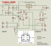
Pay attention that seems the Tubalizer schematic reverse engineered is wrong. No right to publish the original schematic.
But, for people wants to run a 12V buffer with 6SL7, we playing a little bit with spice and we got a simple schematics:
Pay attention that seems the Tubalizer schematic reverse engineered is wrong. No right to publish the original schematic.
But, for people wants to run a 12V buffer with 6SL7, we playing a little bit with spice and we got a simple schematics:
An externally hosted image should be here but it was not working when we last tested it.
Has anybody tried out Alastair's design? Results?
Or for that matter Plovati's? Though that schematic looks a little confusing for me being a complete novice.
I am trying to build a tube buffer for a SI t-amp upgrade.
Or for that matter Plovati's? Though that schematic looks a little confusing for me being a complete novice.
I am trying to build a tube buffer for a SI t-amp upgrade.
Has anybody tried out Alastair's design? Results?
Or for that matter Plovati's? Though that schematic looks a little confusing for me being a complete novice.
I am trying to build a tube buffer for a SI t-amp upgrade.
Well, the parts are cheap and the design is simple. Why not build both? 🙂
If it's confusing then I'm sure you'll find help around here.
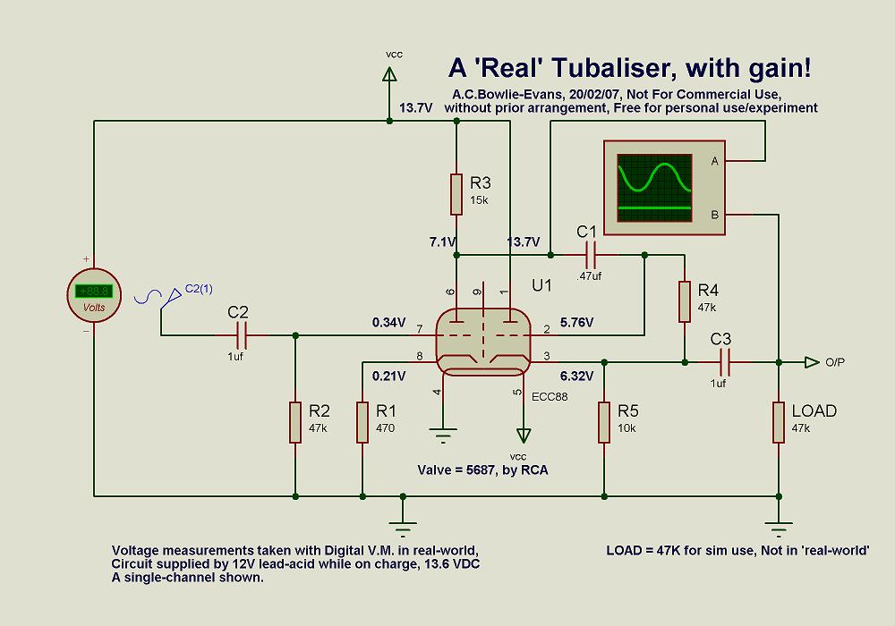
I thought that I would try the 'Real' Tubiliser circuit using a 5687. I've built it P2P and checked that it is wired up correctly but when I power it up I get totally different voltage readings to the ones in the circuit diagram.
Supply is 12.27v from an SLA.
Where the diagram says 0.34V at pin 7 I have 2.93v
Where the diagram says 0.21V at pin 8 I have 2.92v
Where the diagram says 7.1V at pin 6 I have 11.97v
Where the diagram says 5.76 at pin 2 I have 0.91v
Where the diagram says 6.32V at pin 3 I have 0.9v
Can anybody suggest what I have done wrong please?
Unfortunately I don't have any other suitable types of valve to try despite having a big box of old radio/TV valves in the cupboard. 🙁
I think that I may have found my own answer.
Pinout for a 5687 🙄
Is this why nobody has reported back here having the built one? 😉
Back to the soldering iron. Actually no - I can't make out what goes where at all now. Anybody able to help out please?
Pinout for a 5687 🙄
An externally hosted image should be here but it was not working when we last tested it.
Is this why nobody has reported back here having the built one? 😉
Back to the soldering iron. Actually no - I can't make out what goes where at all now. Anybody able to help out please?
Last edited:
Well, there is a descrepency between the two pin outs so I expect that might be part of your problem. One shows a shield on pin 9, the other shows pin 9 as anode of second triode.
Tungsol data sheet:
http://www.mif.pg.gda.pl/homepages/frank/sheets/127/5/5687.pdf
Says heater center tap is pin 8, so if you used schematic it is wired wrong.
1. Print the schematic.
2. strike out the pin numbers for the second triode.
3. write in pin numbers from the small tube pin out.
4. correct wiring to agree with corrected schematic.
I think that will help.
I looked up an ECC88, and that is the pin out in the schematic. Bad news to reference a second tube with a different pin out in the schematic. It implies they are interchangable, which they are not.
When properly wired, your voltages may be slightly different from the ones in the schematic.
Last edited:
Thanks Gimp, as a tube newbie I am still having a bit of trouble but have got to the following:

Am I near? 😕
Am I near? 😕

Coming back to this fresh after a night's sleep, it looks wrong, at least as regards the heater wiring. Surely one heater is just a short across the 0v line and won't power up, while the other one will get the full 12v. 🙁
Ok. I've just built one channel of the circuit below and it works!
Note than pin 8 is not connected as the two heaters are connected in series!

I used a 1uF cap for the input, 1uF for the feedback, and 4.7uF for the output but otherwise I built it the same as the diagram.
After testing, I replaced the 47K load resistor with 220K and then played some music with it. I'm reserving judgement on sound quality until I have two channels, and have done a bit of tweaking.
Note than pin 8 is not connected as the two heaters are connected in series!
I used a 1uF cap for the input, 1uF for the feedback, and 4.7uF for the output but otherwise I built it the same as the diagram.
After testing, I replaced the 47K load resistor with 220K and then played some music with it. I'm reserving judgement on sound quality until I have two channels, and have done a bit of tweaking.
- Home
- Amplifiers
- Tubes / Valves
- 6SL7 or 6SL7GT for broken Tubalizer