Update:
I moved the grid resistors as suggested and it definitely helped a lot. Distortion was still evident but greatly reduced. The trouble is, it sounds better without power!!! Remove the supply and it sounds much clearer!! I tried many different resistor values and lower was better but obviously not desirable. It just made me wonder what was the point in using it if it didn't DO anything? I also tried increasing resistance and re-instating a little grid bias.
In conclusion: This method helped the distortion but also seemed to lose the 'valve' sound.
As mentioned before I've been slowly collecting the parts that I need for a working prototype of Alastair's circuit. Should be in place within a week. 😉 I've also being eyeing up all the old electrical gear in my house that could be converted to into a valve pre (Alastair's circuit). I think I'm looking for up to 40V B+ for now. At least while I'm learning!
My SS integrated amplifier has a passive preamp and therefore a high gain so Alastair's 'real' tubalizer would fit very nicely in my setup. Time will tell.
Today I'd had enough. I decided to turn Kamikaze. I checked the datasheet for the 6 volt reg and found that it can handle Max 35Volts in. The electrolytics are 25V and a bit close for comfort but I hate this thing so much lately that I don't care if I 'kill' it. In fact it may release some anger
I converted it back to 'stock' form but with a 6SN7 (Thanks Alastair) and nervously hooked it up to my 24V bench supply. The result was beautifully clear and undistorted sound! At last!
Messing with the pot didn't change the sound at all so I assume that I had plenty of headroom with the new supply? and that the op point was not so critical.
Why is there a 50KOhm op point adjustment anyway? I would have thought it would be pretty much useless for most people with 12 Volts operation but what do I know? I'm just a tube Noob. A smaller value may have made sense for precise adjustment maybe.
I then tried a 6SL7 with reduced cathode load resistance and I think (in a short listening test in a non optimised circuit) that it had better LF response and clearer highs. I will investigate this thoroughly tonight though. I didn't have much time to listen to it yet.
Well, I'm quite optimistic about the little tubalizer now. It works great, so far, on 24 volts. Maybe it would have worked for me with 14, 16, volts. Who knows? Probably.
I don't know why it didn't work on 12V. I do have a passive preamp which may have loaded the valve too much but I did try it with a simple breadboarded opamp between the Tubalizer and the amplifier. I tried a few amps and mixers and C.D. players with similar results. Is the Tubalizer rubbish? Or am I just unlucky? I guess we'll never know.
I'll continue to run the Tubalizer on 24Volts until I can build Alastair's design. The regulator gets stupidly hot now but should be O.K. temporarily until I separate it from the board and give it it's own supply. I will, of course, change the electrolytics as well.
Finally I'd like to thank you all for the massive amount that I have learned through your help. It has been priceless. Special thanks going to Alastair for posting a design and also posting a valve.
Right, I'm off. This is getting a bit like a speech at the Oscars.
Alastair E said:........ As a test, remove the two grid-resistors, and place them between pins 1-3 and 4-6. of the valve...............Placing them directly at the valve-pins will at least give the valve some grid-bias, as well as neg-feedback to help out with the distortion ........ It may be worth lowering the value to around 33K as well, maybe lower, for best operation.....😀
I moved the grid resistors as suggested and it definitely helped a lot. Distortion was still evident but greatly reduced. The trouble is, it sounds better without power!!! Remove the supply and it sounds much clearer!! I tried many different resistor values and lower was better but obviously not desirable. It just made me wonder what was the point in using it if it didn't DO anything? I also tried increasing resistance and re-instating a little grid bias.
In conclusion: This method helped the distortion but also seemed to lose the 'valve' sound.
As mentioned before I've been slowly collecting the parts that I need for a working prototype of Alastair's circuit. Should be in place within a week. 😉 I've also being eyeing up all the old electrical gear in my house that could be converted to into a valve pre (Alastair's circuit). I think I'm looking for up to 40V B+ for now. At least while I'm learning!
My SS integrated amplifier has a passive preamp and therefore a high gain so Alastair's 'real' tubalizer would fit very nicely in my setup. Time will tell.
Today I'd had enough. I decided to turn Kamikaze. I checked the datasheet for the 6 volt reg and found that it can handle Max 35Volts in. The electrolytics are 25V and a bit close for comfort but I hate this thing so much lately that I don't care if I 'kill' it. In fact it may release some anger
I converted it back to 'stock' form but with a 6SN7 (Thanks Alastair) and nervously hooked it up to my 24V bench supply. The result was beautifully clear and undistorted sound! At last!
Messing with the pot didn't change the sound at all so I assume that I had plenty of headroom with the new supply? and that the op point was not so critical.
Why is there a 50KOhm op point adjustment anyway? I would have thought it would be pretty much useless for most people with 12 Volts operation but what do I know? I'm just a tube Noob. A smaller value may have made sense for precise adjustment maybe.
I then tried a 6SL7 with reduced cathode load resistance and I think (in a short listening test in a non optimised circuit) that it had better LF response and clearer highs. I will investigate this thoroughly tonight though. I didn't have much time to listen to it yet.
Well, I'm quite optimistic about the little tubalizer now. It works great, so far, on 24 volts. Maybe it would have worked for me with 14, 16, volts. Who knows? Probably.
I don't know why it didn't work on 12V. I do have a passive preamp which may have loaded the valve too much but I did try it with a simple breadboarded opamp between the Tubalizer and the amplifier. I tried a few amps and mixers and C.D. players with similar results. Is the Tubalizer rubbish? Or am I just unlucky? I guess we'll never know.
I'll continue to run the Tubalizer on 24Volts until I can build Alastair's design. The regulator gets stupidly hot now but should be O.K. temporarily until I separate it from the board and give it it's own supply. I will, of course, change the electrolytics as well.
Finally I'd like to thank you all for the massive amount that I have learned through your help. It has been priceless. Special thanks going to Alastair for posting a design and also posting a valve.
Right, I'm off. This is getting a bit like a speech at the Oscars.
Good to read you've got such progress Sonus, Alastair deserves some kind of oscar for this...
I haven't had much success in entering the socalled 'fleabay' site where tubes would thrive in abundancy and dozens can be bought cheaply , so I'm thinking of ordering two 5687 tubes for 14EUR. each and leave the (5EUR.) matching, though they also charge 10EUR. transportation...🙁
Or is 38EUR. a really bad deal? Drnd...wish they sold them around the corner...
I haven't had much success in entering the socalled 'fleabay' site where tubes would thrive in abundancy and dozens can be bought cheaply
, so I'm thinking of ordering two 5687 tubes for 14EUR. each and leave the (5EUR.) matching, though they also charge 10EUR. transportation...🙁 Or is 38EUR. a really bad deal? Drnd...wish they sold them around the corner...
v-bro said:..... so I'm thinking of ordering two 5687 tubes for 14EUR. each and leave the (5EUR.) matching, though they also charge 10EUR. transportation...🙁
Or is 38EUR. a really bad deal? Drnd...wish they sold them around the corner...
Seems to be a similar price on Ebay in the UK but maybe you should keep an eye on these (Price is for two):
JAN Philips ECG 5687 WB - Ebay This guy seems to have a lot of these so I bet that he will be sending out 'second chance offers'.
Anyway, my first version would probably be with 6SL7 or 6SN7 since I have just bought some octal sockets. This shouldn't be an issue if I run it at 24V. I plan to eventually get the 5687's and try a 12V circuit just to prove to myself that it can be done.
P.S. 'Alastair's Tubaliser' doesn't sound right. It needs a catchy new name but I'm stuck for ideas. The Al - iminator, Al - uminator?

Martin. 🙂
Just noticed the same seller has them as a 'Buy it now' £19.99 which is ~34 Euros for a pair including postage to your fine country. JAN Philips ECG 5687 WB - Ebay - Buy it now
Maybe 38Eur isn't so bad but these are JAN spec. I don't know if the difference between standard types is very significant for our low voltage use. In fact, I don't know very much at all about tubes ....... yet!
Regards,
Martin.
Maybe 38Eur isn't so bad but these are JAN spec. I don't know if the difference between standard types is very significant for our low voltage use. In fact, I don't know very much at all about tubes ....... yet!
Regards,
Martin.
How about 'the Alastube'?
I think the tubes that were offered to me were the same (it said philips usa) so heck, I'm gonna try it anyway! Let all of you know as soon as I have progress...
Cheers!

I think the tubes that were offered to me were the same (it said philips usa) so heck, I'm gonna try it anyway! Let all of you know as soon as I have progress...
Cheers!
Cobra2 said:
Thanks Arne. What a great site.
I'm reading it now,
cheers.
Sonusthree said:
Thanks Arne. What a great site.
I'm reading it now,
cheers.
Looks to be an OK sort of site, But I cant see any schematics or hints as to the voltage of +B apart from the fact he's using SRPP topology, which I would have thought would have needed more than say, 25V!

Alastair E said:
Looks to be an OK sort of site, But I cant see any schematics or hints as to the voltage of +B apart from the fact he's using SRPP topology, which I would have thought would have needed more than say, 25V!
Here's the schematic:
http://www.lampizator.eu/LAMPIZATOR/photogallery/lampizator ver 1.1 cdr.pdf
The posted schematic is messy & confusing too ( for me anyway). But I really love his enthusiasm. I'm really interested in his philosophy that most CD players are very similar except for the output stages. It's a good antidote for all the debates on this forum about which opamp is the best!
Speaking of which....
Alastair:
I'd really like to use your design as an output stage for my CD player. Do you think it would be suitable? I already tried to simply bypass an AD711 Opamp by replacing it with my Tubalizer buffer but I obviously need more than unity gain!!
In a perfect world I would just love to hook it up directly to the DAC which gives out 1v RMS. I'd probably run it at 24V B+ since you mentioned higher B+ means slightly higher gain.
The DAC's output is differential so would I need another cathode follower before your circuit to convert back to single ended first? This is just a question to see if this approach would be viable.
I know very little little about tubes and I'm frantically trying to learn but there are so many options. Everything is about high voltages and chokes and transformers. I'd like to avoid transformers if possible since they seem to be expensive. Is it possible to use your circuit here?
The (My) Tubalizer buffer is sounding great at the moment. If nothing else it is a good demonstration of how transparent a simple tube circuit can be.
I will be building the Alastair E Tubalizer tonight with 6SL7 at 24V!! Wish me luck!
Best regards,
Martin. 🙂
Gosh, You 'Work' late!
Well, I thought I was the only 'nutter' who worked on valves late into the early hours!
The scheme on the guy's Webpage you pointed to isnt really anything to write home-about. SRPP amps are quite basic and can be refined into a 'Mu' Stage/amp with the addition of a couple of resistors and a cap or two. This has great advantages over a simple SRPP-
-I gave up on the SRPP as a gain-stage some years ago,-It just didnt 'do' it for me. I prefer the Mu amp as it goes some way further to presenting the bottom triode (The Gain amp) with a constant-current, --Which is good....
As to the Differential O/P from your DAC, It May be better to use a Unity gain Op-Amp, to get it into 'unbalanced' format before running it into the scheme as posted. May be better not to complicate things Too Much. The present Op/Amp in the DVD/CD can be used, and its FB resistor altered to reduce its gain to Unity and use the valve CCT to get the gain where you want it Silicon is sometimes better for Some things especially where accuracy is needed in 're-combining'....
The gain at 13.6V is around 4, You can Increase this by increasing the value of the gain-stage Anode-resistor or slightly reducing the value of its cathode-resistor. A gain of 4 however should be More than enough if you plan to run it into a 'standard' amp CD/DVD input.
The higher the +B, will increase the 'Headroom' or the point where the valve-preamp starts to approach clipping. The gain is slightly increased also, but not by much, as the scheme has tons of Local Neg FB, to maintain linearity and reduce distortions at this 'silly' low voltage operation.
Let us know how it sounds, and with the 6SN7 rather than the SL7. I found the SL7 rather 'thin and reedy' in sound quality-really not nice to my taste in this scheme, while the 6SN7 sounded 'Full and Free'--But That is my viewpoint, Yours may be quite different, and Im all for experimentation! 😀
Lovely!!
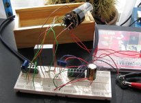
I have made a very rough and ready single channel prototype of Alastair's circuit. At first there was quite a bit of distortion but changing R1 to ~2KOhms sorted that out. I only had ten minutes to listen to it but first impressions are very good.
It works perfectly adequately from 12Volts with a 6SN7. No distortion. 24Volts did seem to give more body to the sound but I haven't had the time (without inquisitive rugrats) for critical tests. That will come later tonight!
I have a couple of questions though:
What influences the capacitor choice in the circuit? Can I just use anything over 1 or 2 uF as long as bass doesn't suffer?
"gain-stage Anode-resistor" & "cathode-resistor".
Could someone point these out on the schematic? I do feel silly for asking.
Kind regards,
Martin.
Attachments
The Anode resistor in the 'gain-stage', is R3, in the scheme, is 10K To Increase the 'gain' Increase this by a few K. The Cathode-resistor in the same stage you have altered already to 2.2K, which has lowered the gain, by increasing 'local' FB.--As I believe the input to the pre-amp you have may be quite high, and instead of altering this value from 1.5K, to 2.2K you could increase the supply by a couple of volts, to give you a little more headroom.
Alternatively, you could-- instead of both cathode-resistors going directly to earth, remove their 'earthy ends', connect them together, and connect them both to the Neg terminal of a 9V battery...PP3 type is good, The Pos. terminal then goes to the earth connection the resistors originally went to...The batt will only discharge during use when the heaters of the valve are on, so it 'could' be a semi-perminent part of the device. Current drain is only around a 1mA or so with the circuit operating, so the batt should last ages...
This will give you around 21V accross the valves, while Still using a 12V +B supply...😀
I chose the caps on the data derived from the sim-work, to give a good phase-response down to around 5Hz. As an alternative to Poly-prop caps, you could use leccylytics. The caps will affect the bass response if they are too small, but anything above around .47uF should give a fair response at low frequencies..
Hi Alastair, everyone,
Thanks for the very helpful reply. I've breadboarded two channels of your circuit. I must say that I agree with you that the 6SL7 sounds worse than the 6SN7. I really enjoyed the sound from the 6SN7 (in mono) but the 6SL7 (stereo) sounds spitty and harsh and the bass is anaemic even with 24V. Some of the issues may be due to the caps that I'm using but I've spent far too long trying to make the 6SL7's sound 'good'. Lowering the gain dramatically doesn't seem to help either.
I'll have to get hold of a pair of 6SN7 and then tweak to suit my system.
In the meantime I think I'll try a similar circuit for a guitar pre/overdrive. I 've really got the bug for low voltage valve stuff.
BTW: I love the 9V battery idea! Ingenious! 😉 I'll try that soon.
How is your in-car version coming along?
Cheers,
Martin.
Very inspiring Martin, all that breadboarding work! 😎
Me, I'm just waiting for the tubes to arrive...but don't expect me to have something up and running within the next week...
Just too busy with other things....🙄
Me, I'm just waiting for the tubes to arrive...but don't expect me to have something up and running within the next week...
Just too busy with other things....🙄
v-bro said:Very inspiring Martin, all that breadboarding work! 😎
Me, I'm just waiting for the tubes to arrive...but don't expect me to have something up and running within the next week...
Just too busy with other things....🙄
Are you implying that I don't have a life?
Being an agoraphobic does have some advantages. 😉
Martin.😀
No, I'm only saying that for the moment....other times (hopefully soon) I will be soldering and testing and listening night and day...🙄
😉
😉
Sonusthree said:
Being an agoraphobic does have some advantages. 😉
Is it serious man?
Ok, I had some time, the valves still didn't arrive so I tested with a couple of audio transformers I rescued from deportation a while ago...
It seems to work pretty well, though at very high levels I do get a bit of distortion....( small 'crackles' on heavy bass passages...).
Overall sound is nice, very 'dynamic'...
http://www.diyaudio.com/forums/showthread.php?s=&threadid=98297
It seems to work pretty well, though at very high levels I do get a bit of distortion....( small 'crackles' on heavy bass passages...).
Overall sound is nice, very 'dynamic'...
http://www.diyaudio.com/forums/showthread.php?s=&threadid=98297
v-bro said:Is it serious man?
Yes. I'll be better soon though, hopefully. It is, by far, the strangest thing that ever happened in my life so far.
Anyway, I managed to get two Russian (1984 OTK) 6SN7 from Ebay for £4.70 delivered. Sounds a lot cleaner than the 6SL7 with more bass and actually quite a neutral tone. Slightly tighter bass with 24V though so I don't think that I would use this on 12V without the extra PP3 battery trick. I must try that soon!
I had to change some resistor values to get rid of some distortion and sibilance but I haven't fully optimised the circuit for the 6SN7. I have listened for two hours today and played with the value of R1 and found that it has to be above ~3K to play undistorted. 10K works quite well also but I settled on 5K for the moment. Maybe the sound would change if I tried lowering R3 a little. Is there an easy way to optimise the ratio between R1 and R3?
So, what would be the best way to convert this circuit to a Hifi preamp with volume control? Just slap a regular 'pot to ground' in front of the whole thing or before the cathode follower?
I'm also keen to try this as an instrument preamp mainly with guitar and keyboards. Could I use a pot to control the gain and should I simply vary R3 or perhaps R1. R1 seems safer and more logical to me but I'm not sure. I'd like to overdrive it a bit as well.
Anyway, Thanks again to everyone here and especially Alastair. I'll be doing some further testing tonight when it's quiet around here and I'll report back.
Cheers,
Martin. 😀
Member
Joined 2002
I like how small and compact this is, looks like a interesting design. Any impressions on the sound so far ?
- Home
- Amplifiers
- Tubes / Valves
- 6SL7 or 6SL7GT for broken Tubalizer