Consumers should not be able to touch hot surfaces
I leave the tube cage off of my customized Dynaco ST-70 series ii, and the power switch is on the back. I think my right elbow has 30 years of burn scars from it. Happened again last week. I try to use my left arm so I can go down the center of the amplifier to turn it off. I am using that amp while I build and test this one. The EL34 output tubes on that Dynaco amplifier are so hot that elbow skin sticks on contact. If I added a rotisserie, I could roast a chicken above it for dinner. 😲
Why wouldn’t it be possible? Unless you constructed it such that you can’t pull the PCB. If you worry about saving expensive transformers from a tube fault it’s simply good practice. It would not have helped a thing in the situation you had, however. The screen never would have drawn enough current to blow anything except perhaps the screen regulator. My biggest amps use active limiting and OVP in the regulator because mosfets have a nasty habit of going short when overloaded. 100 or so ohm screen stoppers aren’t really a help there either, but do prevent local oscillations due to tetrode kink. If added they would probably make it a little better behaved overall. Larger 1k or more screen stoppers defeat the purpose of the regulated g2 supply and if you go that route you might as well just use RC filtering off the main B+. Your overloaded screen would not have caused further harm to the transformer, just killed tube after tube.Had I realized that when I started, I could have made that modification. Now that it is built, it isn't possible.
I would love to know what this bizarre looking version of the same amplifier sounds like. I love the funny looking output tubes! Aren't those wires poking out of the top a little dangerous with no protective cage?
https://www.aliexpress.us/item/3256804993363963.html
The performance in audio amplification is highly praised, and its timbre is described as "ecstasy".
I want ecstacy timbre!
The intermittent at the lugs is exactly the kind of garbage you would get from trying to solder to aluminum wire, and I don’t trust cheap Chinese anything. It looks to me like there was insufficient strain relief which is either a QC or design issue. It might have been why using heat shrink was suggested - to help immobilize things. They may have actually seen this failure before. Good ones will have the connections under the tape, not have magnet wire visible where bends at the lugs can pull on it.
“Ecstasy timbre” from those weird tubes? Nah, I doubt it. They’re just trying to sell something they’d never get rid of in a million years otherwise. The $64k question is are they even made anymore. The $128k question is how close to drying up entire the stock is. I suppose if you had $128k to spend you wouldn’t care. If they end up being rarer than 6LW6’s some day you may have a problem when that set wears out. At least with an octal or compactron socket there is hope of rewiring for a different similar type one day. Those are pretty, but not necessarily practical. If I had a pair for free I might build an amp with them, but not even throw $400 at the entire project because it will be just parted out one day.
Unless you constructed it such that you can’t pull the PCB.
Yes, that is the way it is put together. That's the way the kit is. It would take a lot of desoldering to free the circuit board from the wires entangling it.
A year or so down the road, if I decide that I really like this little amplifier, a new circuit board can be had for only $11. I could populate it with the highest quality parts, make minor design changes such as those suggested here, and even replace the output tranformers with a higher quality pair, for a price of course. I'll see how I feel about the amplifier a year or so from now.
insufficient strain relief which is either a QC or design issue.
The right channel OPT has globs of glue protecting the wires where they exit the transformer and attach to the terminals. The left channel transformer did not get that treatment at the factory.
The intermittent at the lugs is exactly the kind of garbage you would get from trying to solder to aluminum wire
It's copper, and I had no trouble soldering new pigtails to it.
I got the decals on the faceplate, so I may be able to clear coat it and reinstall everything tomorrow for testing after the faceplate is ready to handle again.
The $64k question is are they even made anymore. The $128k question is how close to drying up entire the stock is.
China curently makes the tubes and there are NOS replacements available. People actually do use that tube in amplifiers. Yes, it's a novelty item and possibly a toy instead of a serious audiphile product, but I'd love to hear those weird tubes, which are dual tetrodes apparently.
The tubes look like FU-32 (Chinese version of the 832) , dual beam tetrodes indeed.I'd love to hear those weird tubes, which are dual tetrodes apparently.
It is quite popular in headphone and low power amps.
They are FU32 tubes and they are a modern version of the 832. They have a single pin for the cathodes and a single pin for the screens.
Pete Millet built an SE amp with the 829B (big brother to 832) and was quite pleased with the results.
Steve
Pete Millet built an SE amp with the 829B (big brother to 832) and was quite pleased with the results.
Steve
I watched XrayTonyB's video from the link in the first post. He did 3 videos on this amp.
He discusses all of the components and the schematics. And mentions that the parts are much higher quality than he expected.
He thought he was going to have to make modifications and component upgrades to get acceptable performance. That turned out not to be the case.
The only thing he did not like was the volume control circuitry. The 50k ohm volume pot was in parallel with the gain stages 470k grid leak resistor. This made the grid leak resistance effectively 45k ohm at full volume and downward from their.
He built it per spec and the performance was quite surprising for an under $400 amp. He got 14 watts per channel at clipping. And decided that except for the volume control issue their was nothing else he wanted to changae. And the Chinese version tubes were very good.
Steve
It's been a while since I saw Xraytony's series but I seem to remember he added some grid stopper resistors to the gain/phase splitter tubes. As well, if memory serves, he rotated the OPTs 90 degrees to put their cores at right angles to the power trans.
The only thing he did not like was the volume control circuitry.
Yes, back then the kit had a loudness circuit and switch. That has since been removed from the kit.
I seem to remember he added some grid stopper resistors
He did, but it's not a big issue per earlier posts in this thread, so I have left them out.
... he rotated the OPTs 90 degrees to put their cores at right angles to the power trans.
Yes, he did, but it was pointed out in the YouTube comments section that the PT and OPT coils are at 90 degrees to one another as needed, whether rotated or not.
He built it per spec and the performance was quite surprising for an under $400 amp.
That's one reason why I decided to go ahead and build one. I paid about $350 and then spent about $50 on parts and supplies, so the total is about $400. Yes, the components do seem to be of decent quality, except one very old Philips power supply cap that I spent about $3 to replace just to be safe. I also replaced all of the wiring since I had enough on hand in my giant box of spare wire. The other issue is the possibility of broken or intermittent connections at the transformers, which happened on both my power transformer and left output transformer. As I was putting the repaired output transformer back in place last night, I think I discovered how I caused the problem. When turning the amplifier over with the transformers in place but without the protective cover, it is very easy to bump the transformer tabs on the table. Oops. Don't do that.
Although I have put the repaired output transformer back in place, after a lot of swearing because it's such a tight fit, especially with the PCBs and wiring in place, I have not tested it yet. The DC resistances do measure correctly with everything in place, so I hope everything will work this time. I haven't turned on the power yet. I had a paint compatibility issue on the faceplate, and I had to start the paint and decal work on that over again. It's always something. I couldn't stand the silver painted chassis and brushed aluminum faceplate, so it's all black now.
Last edited:
Is it cause for concern that two of the new Russian 6P14P output tubes have filaments that are inserted higher and lower than the other two? The one on the right is farther up inside, and the one on the left hangs down lower, giving it a much brighter appearance because it's hanging down a little. See picture #3. All four tubes do have the same, correct filament voltage.
I finally got the amplifier back together after repainting the faceplate three times to get a professional result, with wet sanding and multiple clear coats over the decals to get a perfectly smooth finish and no visible edges from the decals. The whole amplifier is satin black, except the front of the transformer cover behind the tubes, which is high gloss black. I went for a minimalist approach on the faceplate, with no words like "Hi-Fi Tube Amplifier" or a logo or name or anything like that. Just white "Power" and "Volume" decals and a white indicator on the volume knob. There already was a notch there fortunately. The horribly smelly paint is still drying, but I got it in place with no scratches or fingerprints. 🙂
All voltages tested within spec this time, as did the DC resistance of the output transformers after repair and reinstallation. It plays music on both channels. That's as far as I have gotten. If it lasts a week this time without blowing up again, I'll then try some critical listening. Fingers crossed. I am hoping that it won't be light in the very deep bass response because that drives me nuts.


The silver made my eyes hurt. Glad that's gone forever! Only the back panel is still silver because it's not visible and I didn't want to do a bunch of decals for the connections back there.

I finally got the amplifier back together after repainting the faceplate three times to get a professional result, with wet sanding and multiple clear coats over the decals to get a perfectly smooth finish and no visible edges from the decals. The whole amplifier is satin black, except the front of the transformer cover behind the tubes, which is high gloss black. I went for a minimalist approach on the faceplate, with no words like "Hi-Fi Tube Amplifier" or a logo or name or anything like that. Just white "Power" and "Volume" decals and a white indicator on the volume knob. There already was a notch there fortunately. The horribly smelly paint is still drying, but I got it in place with no scratches or fingerprints. 🙂
All voltages tested within spec this time, as did the DC resistance of the output transformers after repair and reinstallation. It plays music on both channels. That's as far as I have gotten. If it lasts a week this time without blowing up again, I'll then try some critical listening. Fingers crossed.
I am hoping that it won't be light in the very deep bass response because that drives me nuts.The silver made my eyes hurt. Glad that's gone forever! Only the back panel is still silver because it's not visible and I didn't want to do a bunch of decals for the connections back there.
Last edited:
Can anyone speculate as to the circuit used in this different version of the amplifier? It uses four dual-triode 6N1 tubes and four beam tetrode 6P1 tubes. Why would they need four dual triodes in this circuit? Note the "creative" use of the connection in the center of each tube socket where the LEDs go in other versions of the amplifier. This circuit seems significantly more complicated than the version that I built in this thread with only two of the 6N1 tubes and 6P14 pentode output tubes. I am wondering why they went to this extra effort and what advantage, if any, this approach might bring.


If anyone wants to get one of these kits at a discount, you can get $40 off at AliExpress for about the next 24 hours with this code:
$40 off a purchase of $220 or more promo code HBD40
That takes the price down to about $310 if you look for the less expensive sellers. Don't use the cheapest seller if you expect any service after the sale. I had that problem ... I suggest that you chat with your preferred seller first to see if they are responsive.
I personally translated the current version of the directions (67 pages) from Chinese to English, and a link to them is published in one of the posts somewhere above in this thread. Get them while they are available for download. I can verify that they are correct and sufficiently detailed for a person with only moderate experience to build the amplifier.
Would be nice to cap off this thread by hearing how you feel about this amp. Are you pleased with the outcome? Does it tick the boxes when you listen to music?
It looks like yours has been very well executed, and it has been an interesting journey.
It looks like yours has been very well executed, and it has been an interesting journey.
What was the shipping Cost?
With the promo code, you can get it down to about $310 including shipping to the US. Shipping is about $120 of the $310 cost.
Would be nice to cap off this thread by hearing how you feel about this amp. Are you pleased with the outcome? Does it tick the boxes when you listen to music?
I'm not going to post a full, critical listening evaluation for a couple of months, and this thread likely will be dead by then because this was intended to be a Q and A, and it has gotten very long - so long that others don't want to read it, and I don't blame them. 😵
I find the sound very pleasing so far, and improving daily, but the Russian 6P14P tubes are just now breaking in, and I just ordered 6N1P drivers from Ukraine. I don't know how long they will take to get here. I also need to order a pair of the Chinese 6P14 to replace the one that blew so I can properly evaluate those.
Listening so far: I do think that it will become my permanent amplifier, replacing both my hot-rodded, silver-wired, point-to-point-wired Dynaco ST-70 series ii, as well as my 1,500 watt 5-channel Outlaw Audio solid state amplifier. It's good enough for me to say that right now. However, read below though for mods. Note: my hot-rodded Dynaco easily beat out the solid state Forté, Classé, Adcom, and Threshold 50 watt/channel pure class A amplifers that I owned simultaneously back when I built it in the 1990's, and this little amp may end up being almost as good as my hot-rodded Dynaco, just with half of the power. It wasn't easy to beat that Threshold amplifer IMHO. That was a very expensive amp, about $1,800 back then, designed by Nelson Pass IIRC. I sold it and all the others and kept the hot-rodded Dynaco. Now this likely will replace it.
It looks like yours has been very well executed, and it has been an interesting journey.
I did a number of "hot rods" to it like pseudo point-to-point wiring, special wiring upgrades, better wire routing, and other upgrades. All details were attended to meticulously, right down to the silver solder and custom paint and decal work. I'd like to put a stepped attenuator in it, but that will take time, money, and drilling the faceplate hole larger. When this journey is complete, I will finally post a concise sound quality review stating the test system and the test music used as well as the modifications that I did so anyone interested doesn't have to read this very long thread. If anyone is going to build this amplifier before I post a critical review, please send me a private message to discuss simple hot-rod mods and why you might want to do them yourself.
As for the interesting journey, that was mostly of my own doing. An external bucking transformer could be used to drop the voltage to 110, but I wanted everything self-contained. The broken transformer wiring was caused by me flipping the amplifier during contruction and jarring the tabs on the transformers. Fortunately, they are all fixed now. The chassis could have stayed silver, but I wanted black. The magic eye tubes could have been put in place, but I didn't want those things flashing at me. I didn't want it the way it was, I wanted it my way, and there always is a price to pay for that in time and money. I'm happy now though, and I want to thank everyone who has followed along and helped out.
Let's hope that I'm not back in a few days with any more problems!
Can anyone speculate as to the circuit used in this different version of the amplifier? It uses four dual-triode 6N1 tubes and four beam tetrode 6P1 tubes. Why would they need four dual triodes in this circuit?
I suspect this has something to do with cloning the four dual-triodes of the Dynaco ST-70 series iii, which was a flop due to the $3,000 price tag attached to it. I find the quad-dual-triode version of this kit quite interesting though.
Last edited:
I think it may be possible to build this amplifier in the tight space using something like this: two pieces of fiberglass board (no copper) 2x2" for the input boards and a 3.75x12.5" piece for the power and bias circuitry. It would allow room for circuit modifications and also allow mounting the tube sockets directly to the chassis. This is how I rewired my Dynaco ST-70 series ii to get rid of its circuit board. I just drilled holes in blank fiberglass board and wired point-to-point underneath it. It has worked great for 35 years.
Question: If I use a separate bias resistor and separate cathode bypass cap for each tube, replacing C5 and C6 and R21 and R22 with four caps and four resistors, what would be the correct values? As you can see, this method of construction would allow plenty of room for that.

Question: If I use a separate bias resistor and separate cathode bypass cap for each tube, replacing C5 and C6 and R21 and R22 with four caps and four resistors, what would be the correct values? As you can see, this method of construction would allow plenty of room for that.
Attachments
About separate bias, just double the cathode resistor value, power required will be halved too. Keep the same capacitor value.

But you will need one capacitor per tube, of course.
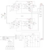
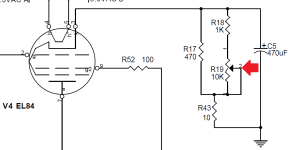
On the other hand, if you have the room and want to tweak the bias on each EL84, you could use the method used on the (discontinued) DIYtube.com Dynaclone. See attached. I use it on most of my EL84 builds. Only the 470 ohm resistor needs to be 1 or 2 watt. Measure the voltage across the 10ohm, 1% resistor and adjust the trim pot for the current you desire.
Steve
Attachments
method used on the (discontinued) DIYtube.com Dynaclone. See attached.
I don't suppose you have the ST-35 build manual mentioned on DIYtube.com? I don't seem to be able to find it there. I'd like to build a clone ST-35 one day even though I have exactly no need for yet another amplifier, but apparently all ST-35 kits have been discontinued. The one at https://www.dynakitparts.com/shop/st-35-kit-120-vac/ looked nice, but apparently they are going out of business. They said they have no plans to restock any of their amplifier kits.
The next time these little Chinese amps go on sale, I might get another one to fiddle with. I love the chassis. I'd buy another kit right now before the $40 off code expires in 10 hours, but time and finances don't really permit. I am so tempted to get another one just to fiddle with. My main goals would be to get the tube sockets mounted to the chassis instead of a PCB, and also to improve the bias method as discussed in the three posts above. There isn't any real "need" to do either, but like a lot of people here, I like to fiddle with things like this! 🙂
Never,
Check your PM.
Some one on eBay is selling Dynaclone boards: https://www.ebay.com/itm/2250663174...uid=wzZzolA2RqW&widget_ver=artemis&media=COPY
If building an one of the Chinese kits I'd build the Tubelab SPP. I built my personal one but with the Dynaclone bias mod.
Cheers, S.
Check your PM.
Some one on eBay is selling Dynaclone boards: https://www.ebay.com/itm/2250663174...uid=wzZzolA2RqW&widget_ver=artemis&media=COPY
If building an one of the Chinese kits I'd build the Tubelab SPP. I built my personal one but with the Dynaclone bias mod.
Cheers, S.
Not that I would do it, but since the ultra-linear taps are already there, could they be used with minor circuit modifications? I wonder why they chose not to?
The amp sounds good so far. In a few days, I'll remove it from the system and retest all voltages. I also have 6N1P and 6N1P-EV tubes on order from Ukraine and a replacement pair of Chinese 6P14 to see how those sound since I blew one right away.
The amp sounds good so far. In a few days, I'll remove it from the system and retest all voltages. I also have 6N1P and 6N1P-EV tubes on order from Ukraine and a replacement pair of Chinese 6P14 to see how those sound since I blew one right away.
- Home
- Amplifiers
- Tubes / Valves
- 6P14/EL84 amplifier kit building questions - before I build - maybe during if I do