If memory serves, the Russian 6N1P have much different parameters than the Chinese 6N1 that came with your amp. The chinese are tubes are closer to the ECC85/6AQ8. The 6AQ8 is kinda sorta a 6volt version of a 12AT7. If it were me, I'd change the heater wiring and a couple of resistors on the input/phase splitter to the Tubelab SPP values and use 12AT7s.
I don't think you will have much joy until you stop using Chinese 6P14 tubes and start using russian-made tubes. If you don't want to buy current production there are a number of vendors selling NOS russian tubes for not very much.
I wouldn't switch to ultralinear while you are still using chinese tubes. UL will likely be putting a higher voltage on the screen grids than they have currently.
S.
I don't think you will have much joy until you stop using Chinese 6P14 tubes and start using russian-made tubes.
I don't have a point of reference yet as I have a mixture of tubes in it right now, but I hear nothing wrong with it as it is. When my 6N1P and 6N1P-EV tubes arrive from Ukraine, I'll be able to compare them to the Chinese 6N1 tubes that are in the amp right now. The 6N1P and 6N1P-EV that I ordered come with basic tube tester results so they can be reasonably matched into left-right pairs. Apparently they do vary a lot.
The power tubes I'm using right now are Russian 6P14P because I blew one of the Chinese 6P14 tubes due to my own error (broken lead on OPT). I ordered a replacement pair of 6P14 from China to go with the remaining good ones. When they arrive, I'll be able to compare the Russian output tubes to the Chinese version. The Chinese 6P14 output tubes don't have a bad reputation for sound quality on Chinese discussion boards, but they do have a bad reputation for quality control on those same discussion boards. The ones from Beijing are the best according to them.
I'd change the heater wiring and a couple of resistors on the input/phase splitter to the Tubelab SPP values and use 12AT7s.
That's an interesting idea, but I have no complaints as it is. Given the way the amplifier is constructed, it would be almost impossible to make that change without building a second kit or discarding the circuit board and starting over point-to-point. I spent some time studying the SPP yesterday to learn more about it, but the last thing I need right now is another amplifier. Yet, for some reason the nostalgia of the Dynaco ST-35 appeals to me so much that I would love to try one just for fun.
UL will likely be putting a higher voltage on the screen grids than they have currently.
It's already running at the 6P14's maximum permissible 300 volts. The question was strictly hypothetical. I was just wondering why the amplifier designer chose not to use the UL taps since they are provided but unused in the design.
If memory serves, the Russian 6N1P have much different parameters than the Chinese 6N1 that came with your amp.
I have translated both the Chinese 6N1 and Russian 6N1P specification sheets. They appear almost identical to me. If anyone needs them for future reference:
6N1 (translated from Chinese)
------------------------------------------
Main electrical parameters
Filament /Heater voltage (~or-) 6.3 V
Filament /Heater current 600 ± 50 mA
Anode voltage (-) 250 V
Anode current per triode 7.5 mA ± 1.7 mA
Cathode resistor per triode 600 Ω
Trans-conductance per triode 4.55 ± 0.75 mA/V
Amplification factor per triode 37±7
Inter-electrode capacitance
Output capacitance of the first triode 1.75±0.35PF
Output capacitance of the second triode 1.95±0.85PF
Transitions capacitance per triode 1.85±0.35PF
Capacitance between two anodes 0.075± 00.125PF
Capacitance between cathode and filament of each triode not less than 5.6PF
6N1 Maximum Values
Maximum filament voltage (~or - ) 6.9V
Minimum filament voltage (~or-) 5.7V
Maximum anode voltage per triode (-) 300V
Maximum cathode current per triode 25 mA
Maximum anode power dissipation per triode 2.2W
Maximum voltage between cathode and filament voltage per triode ±250V
Maximum grid bias resistor per triode 1 M Ω
-------------------------------
6N1P (6Н1П) specifications (translated from Russian):
Voltage
heater 6.3V
anode 250V
Current
heater 600 ± 50 mA
anode 5.6-10.5 mA
Resistance in cathode circuit 0.6 kOhm
Transconductance 3.5 - 5.5 mA/V
Inverse grid current, at resistance
1 MOhm in grid circuit ≤ 1 uA
Amplification factor 35 ± 8
Capacitance
input 3.1 ± 1.1 pF
transfer ≤ 2.7 pF
first triode output 1.6 ± 0.5 pF
second triode output 1.7 ± 0.5 pF
1st triode anode-to-2nd triode anode ≤ 0.2 pF
Limit Values of Operating Conditions
Voltage
heater 6.9V max, 5.7V min
anode 300V
between cathode and heater:
with heater at positive potential 100V
with heater at negative potential 250V
Cathode current 25 mA
Power dissipation at anode of each triode 2.2W
Resistance in grid circuit of each triode 1 MOhm
Last edited:
Still enjoying the amplifier with no problems! 🙂 Whenever my 6N1P-EV tubes arrive from overseas, I'll pull the amplifier out of the system and retest all of the voltages inside.
I went back through xraytonyb's video build series and testing of the amplifier. Based on his tests, if the amplifier was rated at 20Hz to 20kHz with both channels driven right to the point where the waveform distorts on the oscilloscope, he found about 7.8 watts per channel. Above 7.8 watts per channel with both channels driven, the waveform between 20Hz and 30Hz distorts severely.
Question: Is this limited power between 20Hz and 30Hz directly caused by the output transformers, specifically the output transformers being too small to produce any more power in that range without distorting? Is that correct?
If we "cheat" and rate the amplifier from 30Hz to 20kHz, we get about 11.5 watts per channel.
Not that I am complaining. It sounds fine.
Thank you for this thread, I have been reading it with great interest as I have just purchased one of these kits and it has given me a great heads up on things to look out for. I didn't receive any build instructions and hope I will be granted access to the ones posted earlier in the thread. The first thing I have done is make a safety cover as I would not want the grandchildren to injure themselves or worse and also to protect the tubes.


Hello! You are most welcome for the posts, and I especially thank those who gave me guidance and assistance along the way. Are you in the United States with 120 volts AC? If so, pay special attention to the component values that I used to drop the voltages since they are too high when running on 120 VAC. If you have any questions, just post them and I'll answer as quickly as I can.
Update 1: The amplifier sounds fantastic the way I built it, which did include some minor modifications that I have not posted, including pseudo point-to-point wiring that is a cheap and easy upgrade. I always intended to come back to do a build thread showing the modifications and tweaks as well as a listening evaluation, but I have not had time (yet).
Update 2: I found that the amplifier does benefit signficantly from being plugged into a Furman PL-8C power filter. Ordinarily I would not plug a power amplifier into a power conditioner, but since this amplifier presents a relatively constant power draw, unlike a massive solid state amplifier, I found that it does benefit. I have two Furman PL-8C filters. They are available for only $150 on Amazon, and they provide very effective surge suppression for other system components in addition to line conditioning. On one unit I plugged the amp into outlet #1 on bank 1 and my DAC and transport are plugged into bank 2. A second PL-8C protects the TV and other non-audio components.
I'll see if I can arrange that. I have them - 65 detailed pages - translated by me into English, but they are way too large to upload here. Please send me a private message. I also have the tube specifications, also translated by me into English.
I suggest that you go ahead and order a pair of Russian 6N1P driver tubes. Although the included Chinese 6N1 driver tubes are ok, I did find that the Russian 6N1P sounds smoother and more full. They are very inexpensive on Flea-Pay. I have been ordering my tubes from sellers in Ukraine with no problems other than slow speed. I have on order a set of 6N1P-EV driver tubes because they were cheap and have longer life.
I also am using Russian 6P14P output tubes, but only because I blew one of the Chinese 6P14 output tubes. The 6P14P in matched pairs sound fine to me, and they also are not expensive on Flea-Pay. If you don't intend to use the Chinese 6P14 tubes that came with it, I could use them for testing. I have three of them now, which is pretty much useless.
That's a great idea, but I recommend against that design as it will partially trap the heat radiating upward from the tubes. Although it can eventually escape by traveling laterally, you really want an open mesh top, which should be relatively simple to accomplish.
Take special note of my damage to the transformer winding wires at the transformer tabs and subsequent tedious repairs. Don't accidentally bump the tabs during assembly, and heat shrinking them as the instructions suggest may do more harm than good.
I made an all black version of the amplifier, and if you read through the thread, I omitted the flashing magic eye tubes. I intended to upgrade the volume control, but so far I have not. I have been enjoying it as it is.

Update 1: The amplifier sounds fantastic the way I built it, which did include some minor modifications that I have not posted, including pseudo point-to-point wiring that is a cheap and easy upgrade. I always intended to come back to do a build thread showing the modifications and tweaks as well as a listening evaluation, but I have not had time (yet).
Update 2: I found that the amplifier does benefit signficantly from being plugged into a Furman PL-8C power filter. Ordinarily I would not plug a power amplifier into a power conditioner, but since this amplifier presents a relatively constant power draw, unlike a massive solid state amplifier, I found that it does benefit. I have two Furman PL-8C filters. They are available for only $150 on Amazon, and they provide very effective surge suppression for other system components in addition to line conditioning. On one unit I plugged the amp into outlet #1 on bank 1 and my DAC and transport are plugged into bank 2. A second PL-8C protects the TV and other non-audio components.
I didn't receive any build instructions and hope I will be granted access to the ones posted earlier in the thread.
I'll see if I can arrange that. I have them - 65 detailed pages - translated by me into English, but they are way too large to upload here. Please send me a private message. I also have the tube specifications, also translated by me into English.
I suggest that you go ahead and order a pair of Russian 6N1P driver tubes. Although the included Chinese 6N1 driver tubes are ok, I did find that the Russian 6N1P sounds smoother and more full. They are very inexpensive on Flea-Pay. I have been ordering my tubes from sellers in Ukraine with no problems other than slow speed. I have on order a set of 6N1P-EV driver tubes because they were cheap and have longer life.
I also am using Russian 6P14P output tubes, but only because I blew one of the Chinese 6P14 output tubes. The 6P14P in matched pairs sound fine to me, and they also are not expensive on Flea-Pay. If you don't intend to use the Chinese 6P14 tubes that came with it, I could use them for testing. I have three of them now, which is pretty much useless.
The first thing I have done is make a safety cover as I would not want the grandchildren to injure themselves or worse and also to protect the tubes.
That's a great idea, but I recommend against that design as it will partially trap the heat radiating upward from the tubes. Although it can eventually escape by traveling laterally, you really want an open mesh top, which should be relatively simple to accomplish.
Take special note of my damage to the transformer winding wires at the transformer tabs and subsequent tedious repairs. Don't accidentally bump the tabs during assembly, and heat shrinking them as the instructions suggest may do more harm than good.
I made an all black version of the amplifier, and if you read through the thread, I omitted the flashing magic eye tubes. I intended to upgrade the volume control, but so far I have not. I have been enjoying it as it is.
You are referring to these I suppose? They should still be accessible. Let me know if you have problems downloading them.I didn't receive any build instructions and hope I will be granted access to the ones posted earlier in the thread.
Instructions in Chinese: https://drive.google.com/file/d/1S_Yz822MBgqkhp78-bDIAKwqcYnHMlps/view?usp=sharing
Translated instructions: https://drive.google.com/file/d/1iew0VAYs33ILgaCrBOqd0biVfyMwWUHl/view?usp=sharing
Instructions in Chinese: https://drive.google.com/file/d/1S_Yz822MBgqkhp78-bDIAKwqcYnHMlps/view?usp=sharing
Translated instructions: https://drive.google.com/file/d/1iew0VAYs33ILgaCrBOqd0biVfyMwWUHl/view?usp=sharing
I still have access. Thanks for leaving them available. 👍
I'm based in the UK so will be running 230vac. The cover is still a work in progress and was only fitted for a trial fit. I intend to drill some holes in the top surface but want to keep a clear view of the tubes from the front.
I don't seem to have access to the files, but maybe the problem is at my end. I will pursue this further tomorrow and get back to you all should I not be able to solve this issue.
I don't seem to have access to the files, but maybe the problem is at my end. I will pursue this further tomorrow and get back to you all should I not be able to solve this issue.
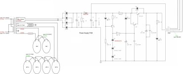
NGO,I am working on the schematic though, which I finally found last night, but due to poor printing, some of the values are not legible. However, when I gutted and rebuilt it, I made a diagram and a list of which resistor was which, and I wrote down all of the values, so I can put clear values on the schematic.
Do you have pic of that power supply schematic with part #'s and values written on it that you can post?
Interested in that regulator section-
Thanks,
Jim
The power supply in the Dynaco ST-70 series ii is different from the one for this amplifier. The power supply for this amplifier and the resistors needed to correct the voltage for USA 120VAC use without a bucking transformer is attached.
Attachments
I'm still unable to access the build instructions and am wondering if this is because I'm still under moderation.
Does anybody have any idea? Or is it just a case of waiting?
Does anybody have any idea? Or is it just a case of waiting?
Hm. Should be available for anyone. I'll look into this tomorrow.I'm still unable to access the build instructions and am wondering if this is because I'm still under moderation.
Does anybody have any idea? Or is it just a case of waiting?
I also have one of these kits sitting on shelf waiting for time to build. I also have wondered if anyone has trying to connect the ultraliner taps up and listen/measure. Perhaps I will have to be the one. In all my reading I am convinced that the output transformers have a larger effect on the sound quality than any other single component. My biggest worry about this kit has always been the small transformer size. Larger cores produce better bass. I have purchased two other output transformers to test during construction to see if there are audible/measurable differences.
Thanks Never Get Old for posting this thread and your experience as you built the kit.
Thanks Never Get Old for posting this thread and your experience as you built the kit.
I also have wondered if anyone has trying to connect the ultraliner taps up and listen/measure. Perhaps I will have to be the one.
The amplifier directions (translated from Chinese) state:
Note: The super-linear taps G1 and G2 of the output transformer are left unconnected in this circuit and do not work.
So, I assume some circuit modification would be required.
As for the size of the output transformers, I think they are adequate for anyone who isn't overly concerned with the power from 20 to 30 Hz. My speakers are about 93dB efficient, and they are solid down to about 24 Hz. After a lot of listening to this amplifier, I find the included transformers perfectly adequate for jazz at a "normal" living room volume level. Per XrayTonyB's bench tests on YouTube, a reasonable rating would be 8 watts per channel, with both channels driven, 20Hz-20kHz. Above 8 watts/channel, the range from 20Hz to 30Hz distorts significantly as shown in his videos. The amp is rated 13 watts/channel 30Hz to 20 kHz, which seems about right.
I bought a pair of 6N1P-EV driver tubes and installed them yesterday to see if they sound any different from the 6N1P drivers that I have been using.
I always meant to come back and create a consolidated build and review thread, but as time goes on I doubt that is going to happen, so here are some more details.
I think I mentioned this before, but I'm not sure that I ever added the picture. I did a pseudo-point-to-point wiring job on the input signal path using silver plated copper wire. I'm not a big fan of PC boards. This approach just requires a little extra care to ensure that all of the solder joints are good. I used standard 2% silver solder. Note that little red jumper at the top of the picture. It's not shown in the directions, but it obviously belongs there if you look at the schematic and the circuit board.
I also took a few minutes to match all of the caps and resistors in pairs to 0.4% or less. It's easy and it doesn't cost anything, so why not? I upgraded the cathode bypass caps to Nichicon Muse, bypassed with small film caps, which was not an expensive upgrade. I had plenty of wire on hand, so every piece of wire in the amplifier got upgraded also, including very heavy wiring to and from the output transformers and very heavy power wiring. One of these days I may upgrade the volume control. It's on my to-do list. However, I have started tinkering with a new Dynaco ST-35 kit that I bought, so it may never happen.
I think this is a great little amplifier the way I built it, which is why I am not in any hurry to build the new Dynaco ST-35 kit that I bought. I can't say that I have any complaints about this amplifier, which, considering that I only invested $400 including tax, shipping, and upgrades, is remarkable I think.
Why not build the kit as it is? You are probably going to be in for a great deal of frustration especially since it has been a while since you built anything.
Why not build the kit as it is? You are probably going to be in for a great deal of frustration especially since it has been a while since you built anything.
Mine is already finished. The only frustration for me was when I accidentally broke the transformer windings from their connection tabs, which was a real headache to troubleshoot and repair, but which was entirely my fault. Details are posted somewhere in the middle of this thread.
- Home
- Amplifiers
- Tubes / Valves
- 6P14/EL84 amplifier kit building questions - before I build - maybe during if I do