Unsolder and remove the wiring from the P1 terminal. Scrape or sandpaper the end of the internal wire to remove any possible residual enameling that might be causing the open. Resolder, say a Hail Mary, and retest. If still open, you've done all that can be done to save it.
Easy now that it's out. Done as described. Still open. Transformer is officially dead now.
However, there is no point in proceeding if this is just going to happen again for some reason that cannot be identified. Unknown gremilns running around = bottomless money pit and endless frustration.
Back to this point again. I have no idea how or why this happened or what might be done to keep it from simply happening again even if the factory in China does find me a matching output transformer to replace it. No definite (or 95% likely) cause = no real solution, just a gamble I probably am not willing to take.
I was wrong. The B+ end of the winding could also be unconnected. If the same treatment applied to it doesn't help, then you're well and truly toast.
All good fortune,
Chris
All good fortune,
Chris
The B+ end of the winding could also be unconnected.
I already checked that as I was working on it. I checked all three to be sure. It is dead.
What a major disappointment this project turned out to be. I guess where I went wrong was proceeding when I knew there was a left channel problem between pins 7 and 7 on the very first power up test with all tubes in place. I still have no idea what would have caused that. The directions never said to test that, so I never would have known if I hadn't happened to test it in hopes of matching tubes.
Last edited:
Many push pull amps will run, ie, play music with one tube pulled. Not at full power, but at low enough power you might not have noticed. It would act the same with one side of the trafo open.
I actually ran the amp at what I believe to be full power a few times (really, really, really loud) to set the output of my DAC to the point where I just achieved what I believed to be maximum output from the amplifier.
Did you put heat shrink on the OPT tags like you did the power transformer? I had some good cheap transformers from Ask Jan First (an option for you since they'd probably fit), but I had to be very careful with the thin winding wires and how they were attached to the tags.
You talk a lot about measuring current in your amp, but I think it is better to measure voltages, and derive the current from voltage drops across components. It is easy to turn a multimeter into a yellow brick on the current setting with the voltages in an amp.
A good sanity test when it is first built is to draw a chart if tubes Vs pins then add all voltages to earth for all the pins, then turn off and review the data. In the meantime if anything is well off, or a tube is redplating, then stop and turn off.
If you are going to make a habit of building tube gear then a Variac is really useful, helping catch issues before voltages get too great.
Maybe that damn transformer is wound with aluminum wire. Regular solder doesn’t stick to it properly and the act of soldering it into the amp in the first place could have “disconnected” the wire from the terminal(s).
if you look into the joints at the terminals and do find aluminum (or CCAW) wire, then call it lesson learned and get two new trafos from some place “reputable”. If it was a sloppy solder job on copper you can fix it. If it was just poor design you needed better trafos anyway. In any case, fuse the cathodes so a shorted tube can’t take out a new trafo. It will only happen if you get a tube arc - but some people around here have been known to push things till they do. A cathode resistor that will open up on severe overload qualifies - and is the easiest/best method.
Maybe it was working properly for a while right after first turn on, and opened “later”. A bad solder joint could very well do that (and Al wire with the wrong solder mix qualifies as ”bad”). Unless there is a mechanical problem, trafo windings don’t just open up without overheating. That overloaded screen does not draw current through the transformer so it couldn’t have burnt it out.I actually ran the amp at what I believe to be full power a few times (really, really, really loud) to set the output of my DAC to the point where I just achieved what I believed to be maximum output from the amplifier.
if you look into the joints at the terminals and do find aluminum (or CCAW) wire, then call it lesson learned and get two new trafos from some place “reputable”. If it was a sloppy solder job on copper you can fix it. If it was just poor design you needed better trafos anyway. In any case, fuse the cathodes so a shorted tube can’t take out a new trafo. It will only happen if you get a tube arc - but some people around here have been known to push things till they do. A cathode resistor that will open up on severe overload qualifies - and is the easiest/best method.
Maybe it was working properly for a while right after first turn on, and opened “later”.
There was a definite difference of ~22 to 26mA across pins 7 on the left channel and 0mA on the right channel, from the very first moment I turned it on. So far, nobody has been able to explain what would cause that or what to do if it happens again. It ran like that for 48 hours before self-destructing. If I put in a new transformer and it measures that way again, I have no idea what to do or what would cause it.
This is the only place in the amplifier where I did any current measurement. It was suggested by another member for purposes of tube matching.
Maybe that damn transformer is wound with aluminum wire.
It's copper. There is no funny business like aluminum wire there. They may not have the best quality control on the transformers, which are a little rough in appearance, but otherwise the components in this kit are of good quality, and it measures quite well on the bench (see YouTube video series), when it works that is.
Did you put heat shrink on the OPT tags like you did the power transformer?
Yes, and I checked to make sure that didn't dislodge the wire as it did with the power transformer. All of the leads from the windings are there, and I actually resoldered them to the tabs on the transformer last night after I removed it, just to make sure, as advised by another member. The transformer is officially dead internally. That half of the winding is open for some reason somewhere inside. Thes transformers have ultralinear taps that are unused. I am wondering if those connections internally have something to do with the issue. More internal complexity = more can go wrong.
A bad solder joint could very well do that
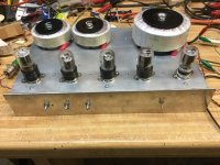
No idea how to figure out if that's the case. The six connections on the circuit board where the wires run to the two transformers all look normal, and the solder flowed properly. If I get another transformer, I can resolder them to see if it makes a difference next time, but that would be guesswork. The solder joints for P1 and P2 are extremely strong due to reinforcing with solid wire jumpers that run on top of the board. Those solid wire jumpers wrap around the wire and run directly to the pin on the tube socket to make a strong connection. Here is the photo from the directions showing how the solid wire jumpers work:
Their solder joints look terrible because of the flux and the lead-free solder. I hate that lead-free stuff and I don't use it. The Kester 2% silver solder that I use doesn't have the brightest finish either, but I haven't ever had a bad solder joint with it after ~30 years of use.
It will only happen if you get a tube arc
The Chinese 6P14 is not known for quality control, and according to my rersearch it is completely unable to handle anything over 300V on the grid, which is why the amp has a 300V regulated supply to control it. I am wondering if it did arc. I may crack open the tube to have a look at the internals out of curiosity. I haven't ever broken open a tube before.
Still no idea why there was ~22 to 26mA across pins 7 on the left channel and 0mA on the right channel, from the very first moment I turned it on. So far, no answer on that, and it's the only clue I have that something was wrong right from the very first instant.
I don't think the presence of the UL taps isan issue, never read that before, but if you have UL taps at least you can pinpoint on which side of the tap the break in the winding is.Thes transformers have ultralinear taps that are unused. I am wondering if those connections internally have something to do with the issue. More internal complexity = more can go wrong.
I do not think adding the heat shrink tubing was a good idea. What was the reason for doing it?
Heatshrinking the mains connections on the primary side of the power transformer (switch, fuse, power inlet) is a different story because that side of the traffo is not isolated, but those connections on transformer windings are very delicate, and a bugger to fix.
I do not think adding the heat shrink tubing was a good idea. What was the reason for doing it?
The directions said to do it, and I didn't even think about it. It did cause the problem with the power transformer HV output, but that wasn't the problem here. I haven't done this before, so I didn't realize that the wires are so thin. Live and learn.
Is there an extremely simple way to use a fuse to avoid this in the future? For example, a single fuse on the 275V output from the power transformer or fuses inline with the center of each output transformer primary?
I still have no idea what caused this.
Last edited:
Cathode fusing is the safest method. The fuse goes in series with the common cathode RC.
Unfortunately, that would be difficult if not impossible to implement now that the amplifier is already built on the PCB. I was hoping that there is a way to do it at the output transformer, where I do have a little bit of room, and the wires are easily routed to a fuse holder, and there is a little bit of room to work with. There is no room inside the tiny chassis, which is packed tight.
The question may be moot as the factory has not yet located a matching output transformer. I did find a pair for $100 delivered, better than the $140 pair I was quoted previously, but I don't want to dump another $100 into this project only to have it blow up again. I'm not sure what my plan is at this point. Still no idea why it happened.
Available real estate for adding fuses:
As already mentioned above, a miiliAmp meter isn't really a safe way to measure this, just for future reference. Not relevant to the problem, but best practice is to use a voltmeter.Still no idea why there was ~22 to 26mA across pins 7 on the left channel and 0mA on the right channel, from the very first moment I turned it on. So far, no answer on that, and it's the only clue I have that something was wrong right from the very first instant.
But to your question, what this means is that the OPT primary was open at the time you made this measurement. The amplifier channel operated well enough with only the other output valve conducting, because our audio processing is actually very forgiving. Golden Ears Gurus would be offended to consider this reality, but it's a result of millions of years of optimization, so they need to get over themselves. G2 continued conducting (too much) and melted.
Consider this scenario: winding a transformer like this is done onto a bobbin with two "parallel" cups for the wire. (We know this because the resistances are so equal). The simplest way to connect the wires on each side of the "UltraLinear" tap is at one of the external terminals. This is another possible location of the open, so must be checked. Resistance tests from here to B+ and anode ends was requested above, but not reported. In this scenario, where is the most likely source of a failure? Possibly the winding tension was so high as to break a wire somewhere inside the densely packed winding, but much more likely the fragile wire ends could fail where brought out or where connected.
No use crying over spilled milk that a $400 Chinese amplifier has flaws. Exhaust all possibilities first, including the (new information) "UltraLinear" taps/ winding connection points.
All good fortune,
Chris
Never,
Might you consider replacing the OPTs sourced closer to home?
Antek has toroidal outputs:
10 watt, 8,000 ohm, $44 each https://www.antekinc.com/mp-10w80-audio-output-transformer/
15 watt, 7,500 ohm, $55 each https://www.antekinc.com/mp-15w75-15w-output-transformer/
Or a more conventional Edcor 10 watt, 8,000 ohms, $87 each,https://edcorusa.com/collections/tu...ube-output-transformer?variant=41462356574395
Assuming of course there is space to fit them.
S.
The simplest way to connect the wires on each side of the "UltraLinear" tap is at one of the external terminals. This is another possible location of the open, so must be checked ... likely the fragile wire ends could fail where brought out or where connected.
You, sir, deserve a trophy. 🏆🏆🏆🏆🏆
I had no idea that each ultralinear tap has not one but two wires from the windings. I assume that one wire of the winding comes out and the other wire goes back in, using the tab to connect the two. I always assumed that it was just a single wire that was there for no purpose if it was not used.
So, what happened? It turns out to have been among the worst possible electrical situations (for me) - an intermittent connection. Very close and careful inspection and further testing this morning revealed that even the slightest touch of the ultralinear tab on the open side of the transformer made intermittent contact. What a mess that made, as we have seen. I teased back the braided insulation as gently as I could using fine sewing needles so as not to disturb the two wires. They were both laying up against the tab but had broken loose from it. It could very well have been making contact one minute and not the next when I was listening to the amplifier. Heating up the transformer over the course of the 48 hours that it ran, and shifting the amplifier around in the cabinet to get at wiring behind it, which I did a few times, could have been enough to make or break that contact. To make matters worse, I discovered this condition on BOTH of the ultralinear taps! It was merely luck that as I have been testing the transformer over the past few weeks that it was always making contact on that tab.
So, I did to this transformer exactly what I did to the high voltage tab on the output transformer when that winding came loose from its tab. I wrapped a strand of fine copper wire around a needle to make a pigtail with 4 turns of wire and a 1/2" lead. I soldered one of these pigtails onto the exposed pair of wires of each ultralinear tap and then wrapped and soldered the tail to the tab. The resulting connection seems to be quite solid. I also didn't like the appearance of the connection at the center, so I put a reinforcement wrap around that one as long as I was at it and soldered that. Better safe than sorry.
The transformer now tests just fine for DC resistance. Live and learn.
Now I'm concerned about the other output transformer. I don't know if I want to go with the old saying if it ain't broke don't fix it, or if it may very well have the same problem with its ultralinear connections and it just hasn't showed itself yet. I'll have to examine it very carefully to see if it warrants removal of the transformer and the same treatment. Of all of the problems I thought I might have, this is one that never even crossed my mind.
I redid both ultralinear taps on the bad transformer with pigtails like this:
No use crying over spilled milk that a $400 Chinese amplifier has flaws.
I am glad that I am learning these things with a $400 kit instead of a more expensive one. I haven't complained at all about any of the components in the kit except the provided wires and one very old Philips power supply cap they included. It tested ok, but as long as I was ordering from Mouser, I replaced it for about $3 to be safe. I do wish the transformer wiring was done a little better at the terminals somehow, but everything else seems just fine.
Now I have to examine the other output transformer and determine if it needs attention. I took this opportunity to remove the faceplate from the amplifier to paint it black as I had planned. It will take several days to do the paint and decal work on that before I can consider putting everything back together again. If the factory in China finds a matching output transformer, I already agreed to buy it for $50 delivered, even now that I have repaired this one. I had no idea that this one could be fixed. They have already gone to significant trouble, so if they find one, I will buy it from them. I can just stick it in my parts box with everything else I have accumulated over the years. Who knows when it might come in handy for something.
Assuming of course there is space to fit them.
I now hope that I won't need them. There is exactly zero room on this chassis for anything other than exact replacement transformers.
Last edited:

What are the outside to outside dimensions of the transformers?
If the manufacturer falls through, there are other options. Knowing the footprint helps.
If the manufacturer falls through, there are other options. Knowing the footprint helps.
If the one that I just repaired works when tested, then I won't need a replacement(s). I won't know for at least a few days while I finish the paint and decal work on the front panel and then put the repaired output transformer back in place for testing.
I examined the other output transformer out of concern for the same issue, and apparently there was a quality control issue. The other one has large globs of glue around each wire where it exits the transformer winding and attaches to its tab, encasing and protecting the connections. The one that I just repaired because of the issues has no glue. I will not fiddle with the one that has all of the protective glue. If it ain't broke, don't fix it.
I examined the other output transformer out of concern for the same issue, and apparently there was a quality control issue. The other one has large globs of glue around each wire where it exits the transformer winding and attaches to its tab, encasing and protecting the connections. The one that I just repaired because of the issues has no glue. I will not fiddle with the one that has all of the protective glue. If it ain't broke, don't fix it.
There is practical benefit to use something like a 10 ohm 0.4W resistor in each output stage cathode, both to allow independent cathode current measurement for each tube, and hopefully act as a poor-man's fuse. Valves may not be well matched, and over time a well matched set can go out of balance, so practical periodic maintenance measurement of balance is in your best interests going forward. In your situation it would also have avoided misinterpreting voltage measurements made elsewhere. Your pcb may easily allow such a retrofit, although I can only see one side of the pcb in post #21.
There is practical benefit to use something like a 10 ohm 0.4W resistor in each output stage cathode, both to allow independent cathode current measurement for each tube, and hopefully act as a poor-man's fuse. ... Your pcb may easily allow such a retrofit, although I can only see one side of the pcb in post #21.
Had I realized that when I started, I could have made that modification. Now that it is built, it isn't possible.
I would love to know what this bizarre looking version of the same amplifier sounds like. I love the funny looking output tubes! Aren't those wires poking out of the top a little dangerous with no protective cage?
https://www.aliexpress.us/item/3256804993363963.html
The performance in audio amplification is highly praised, and its timbre is described as "ecstasy".
I want ecstacy timbre!
Here I sit waiting for the black laquer (very smelly) to dry on the faceplate so I can decal it and put my amplifier back together to test my repair work on the output transformer. Maybe I can get it back together by Friday. I'll have the only all-black version of the amplifier on Earth. Black paint sounds better, right? ; 😉
Last edited:
"Aren't those wires poking out of the top a little dangerous with no protective cage?"
Consumers should not be able to touch hot surfaces or exposed wiring - but that is all encompassed in country standards, which may not apply if the owner purchased equipment eg. on ebay or as a kit or as a DIY project - you take on the risk yourself. A hot surface is typically > 50-70C, so even the input stage valve glass is going to be hotter, and certainly the big triode glass is. The conductive portion of the anode wiring may not be 'touchable', and the lead wire may have sufficient insulation thickness to be deemed acceptable, but who knows 🙁. That is why countries impose regulations on electrical equipment - to reduce the number of Darwin awards given out each year.
Consumers should not be able to touch hot surfaces or exposed wiring - but that is all encompassed in country standards, which may not apply if the owner purchased equipment eg. on ebay or as a kit or as a DIY project - you take on the risk yourself. A hot surface is typically > 50-70C, so even the input stage valve glass is going to be hotter, and certainly the big triode glass is. The conductive portion of the anode wiring may not be 'touchable', and the lead wire may have sufficient insulation thickness to be deemed acceptable, but who knows 🙁. That is why countries impose regulations on electrical equipment - to reduce the number of Darwin awards given out each year.
- Home
- Amplifiers
- Tubes / Valves
- 6P14/EL84 amplifier kit building questions - before I build - maybe during if I do