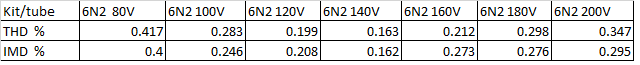
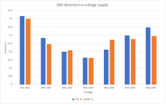
Here is summary of the 6N2 tube in SRPP circuit with various power supply voltages. Agrees perfectly with what others said.
Attachments
Last edited:
According to member Burnedfingers, this is not diy audio project and does not belong here, since i did not design the circuit, etch the board, i simply purchased the kit. I will no longer post any findings. This thread is closed.
LOL. Take no notice of trolls. You are doing some interesting investigations and learning a lot. One thing you need to know is that SRPP distortion depends on the attached load. You might like to try a range of loads with each tube to see how this varies. Also, with all tubes, distortion varies with output level. So it is possible that, if you test a higher gain tube with the same input signal as you used on a lower gain tube, the higher gain tube may appear to have more distortion simply because the output level is higher.According to member Burnedfingers, this is not diy audio project and does not belong here, since i did not design the circuit, etch the board, i simply purchased the kit. I will no longer post any findings. This thread is closed.
In other words, you need to specify output signal level and the load in order to make valid comparisons between tubes.
Cheers
Ian

Haha! No posts by Burnedfingers here. What happens when you go to another thread stays there. Just carry on!According to member Burnedfingers, this is not diy audio project and does not belong here, since i did not design the circuit, etch the board, i simply purchased the kit. I will no longer post any findings. This thread is closed.
Last edited:
Ian, i fully agree that each tube has different gain and the resulting signal level might be different.LOL. Take no notice of trolls. You are doing some interesting investigations and learning a lot. One thing you need to know is that SRPP distortion depends on the attached load. You might like to try a range of loads with each tube to see how this varies. Also, with all tubes, distortion varies with output level. So it is possible that, if you test a higher gain tube with the same input signal as you used on a lower gain tube, the higher gain tube may appear to have more distortion simply because the output level is higher.
In other words, you need to specify output signal level and the load in order to make valid comparisons between tubes.
Cheers
Ian
However, i tried to compensate for it. I use right mark audio, as the rew is setup for mic and speaker stuff. I tried to have receiving signal into the card between -5dB and -10dB of cards max input, as to see best the noise floor and harmonics. This i tried to maintain for all the tubes by adjusting input signal. I tried to compensate for different gain as best i could, still it nothing absolute.
Often i have seen few dB level difference between channels, and that bothers me, as I can hear it.
I did no experiments when it comes to the load.
Thanks for the comment.
I am still working on getting the hum down below 74dB. Not that i hear it, but it affects measurements.
I was being sarcastic 🙂Haha! No posts by Burnedfingers here. What happens when you go to another thread stays there. Just carry on!
Will do!
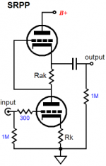
1) Since this is a pre get rid of that 47uF cap. Distortion will be lower.I have one of those boards/kits. The one I have is a very standard SRPP circuit with a gain in or around 30. Sounds very good with 6n2p-ev in place (mine is the 6n2 version). I think I replaced the cathode cap in it as far as I remember
View attachment 1005159
2) I'm fond of the 2C51 / 5670 / 6N3P-EV. All sound slightly different, you can find them in some CD players and Finale Audio has these in one of their $$$ pre. The GE 5 white star 5670 is highly regarded in some circles and has become sought after. There are millions of them (a rugged tube designed for use in the military, tanks and fighter jets)and you can pick up NOS cheap, a few dollars at the most. I like to run them around at 6mA @ 130 - 150V, YMMV.
hi EL506, I will definitely try to measure distortion with and without the cap. Will report back.
Right now I still want to try few dc adapters for heater supply, as to see if I can reduce the hum.
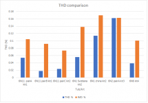
I was testing some of the 6N2 and 6N1 in another board, X-10D musical fidelity buffer, completely different circuit, but it runs much lower voltage so I was curious. Svetlana 6N1 had lower distortion that rest of the maker unknown military 6N2 I have. I do have bunch of 6N2, and there are at least three groups, with different looking inside, some shiny squares, some squares with ridges, some grey looking squares. I did notice distortion figures were slightly different between the groups.
Right now I still want to try few dc adapters for heater supply, as to see if I can reduce the hum.
I was testing some of the 6N2 and 6N1 in another board, X-10D musical fidelity buffer, completely different circuit, but it runs much lower voltage so I was curious. Svetlana 6N1 had lower distortion that rest of the maker unknown military 6N2 I have. I do have bunch of 6N2, and there are at least three groups, with different looking inside, some shiny squares, some squares with ridges, some grey looking squares. I did notice distortion figures were slightly different between the groups.
Just one more observation, I know its apples to oranges, SRPP is a pre and X-10D is a buffer...but at levels matched, SRPP definitely sounds better.
As EL506 suggested, i measured distortion with and without the 47uF cap. While the gain dropped a little, distortion dropped a little too. I adjusted input signal to measure at the same level.
I am using 6N1P Svetlana for this.
Distortion lowered from 0.050% to 0.033%. Intermodulation dropped too.
For some reason even background hash got lower. Pleasant finding, but not sure why.
I am using 6N1P Svetlana for this.
Distortion lowered from 0.050% to 0.033%. Intermodulation dropped too.
For some reason even background hash got lower. Pleasant finding, but not sure why.
Attachments

An unbypassed cathode resistor works as negative feedback, or also known as a form of cathode feedback. I'm fond of using a cathode feedback loop using a winding on the output transformer in addition of UL.
John Brosky of Glassware uses totally different SRPP values (also takes the B+ voltages into account, optimised for each tube), I cannot reveal them as they are proprietary to his SRPP+ module.
John Brosky of Glassware uses totally different SRPP values (also takes the B+ voltages into account, optimised for each tube), I cannot reveal them as they are proprietary to his SRPP+ module.
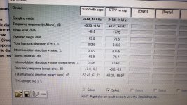
More work being done. I finished two kits into final enclosure. This is one i call 'blue', guess why. I am posting results of distortion before and after cathode bypass cap removal. Significant improvement.
Attachments
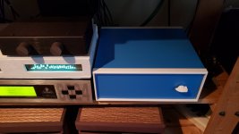

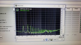
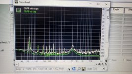
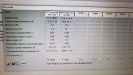
This is the kit i call 'white'. Its foamcore, but power supply is in separate box, and the wireing is shielded audio cables rather then twisted wires. This kit has lowest distortion so far. I am posting before and after cap removal. And background as comparison to previous blue kit.
Attachments

I tried on the kit not in the box, but on the floor, at least five different options for heater, ac, dc, switching supply, normal transformer. There were big differences.
However, adding more capacitance to high voltage had bigger effect, hence you see in 'white' kit i added some more caps.
I will keep experimenting.
Cheers.
However, adding more capacitance to high voltage had bigger effect, hence you see in 'white' kit i added some more caps.
I will keep experimenting.
Cheers.
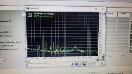
The difference in mains fundamental between the two clearly demonstrates the benefits of screened cabling and remoting the power supply.
The second and higher mains harmonics are most often due to insufficient HT smoothing. The SRPP has a really poor power supply rejection ratio: 6dB with the cathode bypassed, even less without, so you need a really well smoothed HT supply. A series of three RC stages after the reservoir capacitor is the most effective and economic way to achieve this. Three stages are much more effective than a single RC stage, even if the total resistance and capacitance are identical. For example a single 3K resistor and a 660uF capacitor will give about 63dB of attenuation at 120Hz. But three stages of 1K and 220uF will give you 133dB of attenuation at 120Hz and 220uF caps will be a lot cheaper.
Also make sure you snub the HT rectifier as switching spikes propagate only to easily into the audio path.
Cheers
Ian
- Home
- Amplifiers
- Tubes / Valves
- 6N1, 6N2, 6N11 (6DJ8) in pre?