A1-
I like DC on preamplifier stages, AC on power stages in a push-pull amplifier. I wouldn't bother with an external transformer unless the one you have is running too hot for comfort.
A2-
Cathode followers are non-inverting.
A3-
It may interact with your tone controls, but probably not much to be concerned with.
A4-
Most likely, but 12AX7 are not an Ideal triode for such a use anyway, I'd try a 100k load resistor instead of the 18k you have.
A5-
Other than that it looks pretty good, I'd still replace your first 12AX7 with a 12AT7 though, but that's just me. If you can, try some feedback, and try unbypassing that cathode resistor on your first gain stage. Cathode capacitors increase gain, but also increase distortion.
Last edited:
A1-
I like DC on preamplifier stages, AC on power stages in a push-pull amplifier. I wouldn't bother with an external transformer unless the one you have is running too hot for comfort.
A2-
Cathode followers are non-inverting.
A3-
It may interact with your tone controls, but probably not much to be concerned with.
A4-
Most likely, but 12AX7 are not an Ideal triode for such a use anyway, I'd try a 100k load resistor instead of the 18k you have.
A5-
Other than that it looks pretty good, I'd still replace your first 12AX7 with a 12AT7 though, but that's just me. If you can, try some feedback, and try unbypassing that cathode resistor on your first gain stage. Cathode capacitors increase gain, but also increase distortion.
I don't have any other tubes. I'm going to a ham fest this weekend and planed on grabbing a few of the AT, AY, AV, and AU tubes.
If I remember right I tried eliminating the bypass cap and without it low end suffered. I'll verify.
What I'd like not to be doing is compensating one design flaw by adding another. My distortion could be caused by OPT saturation. Considering I have alot of gain, large plate voltages, and fairly small output transformers, it wouldn't suprise me. Maybe a 12AT7 in the PI could help with that as well. I wish I could find my signal generator. I've misplaced it. 😡 That renders my scope useless other then checking for noise. I used it in cars to find rattles. Hopefully it didn't get left in a trunk.
I picked up some 12AU7 (ECC82 Philips). Are these drop-in (see last schematic) or are there adjustments that need to be made?
lower the plate resistance and they may work well, not sue if it would change the frequency response of the tone control though.
Can someone explain the current flow through a tube for me? I'm not understanding why a smaller plate resistor decreases gain. Since this resistor is supplying the output power (common cathode) how does making it larger produce more voltage output? Does it force the tube to conduct more to ground?
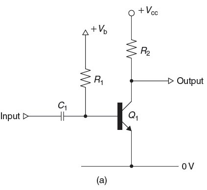
When I see a tube in common cathode I think of this circuit.
 http://www.diyaudio.com/forums/attachment.php?attachmentid=189634&stc=1&d=1285566620
When I see a tube in common cathode I think of this circuit.
Attachments

It seems that if I don't understand all of it, I'll understand none of it. @.@ This might not be my cup of tea. I could look at 100 "load lines" and have no idea what I'm looking at. I can see each piece but not the whole puzzle.
For the same change in current through the valve, a higher value anode resistor will give a greater change in voltage across it (ohm's law). I was hoping the pdf might give you the whole picture.
For the same change in current through the valve, a higher value anode resistor will give a greater change in voltage across it (ohm's law). I was hoping the pdf might give you the whole picture.
I don't understand how more available current (smaller resistor) produces less output. Even in your statement "a higher value anode resistor will give a greater change in voltage across it" should mean less change across the tube. I'm looking at the tube as one half of a voltage divider. So if the anode resistor had say 200v across it (300v B+) then there's 100v across R2 (the tube). If the anode resistor had 100v across it (smaller value) then there's 200v across R2. See how I'm looking at this?
Last edited:
I didn't understand how more available current (smaller resistor) produces less output.
Imagine the triode to be a signal generator in series with a resistance (equal to the internal anode resistance). This forms a potential divider with the external load resistance. The smaller the external resistance, the smaller the output voltage from the potential divider.
L>Can someone explain the current flow through a tube for me?
The collector of Q1 provides no feedback, it merely passes current.
Linearity is highly dependant upon an emitter resistor for feedback,
and driving a blindly assumed linear resistive load.
Difference is plate of V1 provides voltage feedback via internal Mu.
Voltage drop across the triode is linear without a cathode feedback.
Mu can "see" what the load does, and adapt to handle a somewhat
less than linear load.
Read: OHSchade, RCA 1938, Beam Power Tubes.
Transforms Pentode curves into Triode curves in his famous Fig35.
Trying to better explain a Pentode, has also explained the Triode.
There is little mystery why Mu exists after this.
Last edited:
Here's what I'm seeing. In this example a switch is used to represent a valve that can be fully opened and fully closed. The swing between the 2 states is 0 to Vout. A smaller R-plate (in this example) would give a larger V-out.
Vout= B+*Rplate/(Rplate+Rload) ?
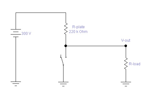
Vout= B+*Rplate/(Rplate+Rload) ?
Attachments

Last edited:
Your circuit is too simple, which is why it doesn't reflect reality. You need to add a resistor in series with the switch to represent the valve's internal anode resistance. Then you should find that although the voltage can be pulled up to 300V (more or less) when the switch is open, it cannot be pulled all the way down to zero when the switch is closed. Increasing the load resistor allows the output voltage to be pulled down further (closer to zero), which basically means more voltage gain.Here's what I'm seeing. In this example a switch is used to represent a valve that can be fully opened and fully closed. The swing between the 2 states is 0 to Vout. A smaller R-plate (in this example) would give a larger V-out.
Last edited:
Your circuit is too simple, which is why it doesn't reflect reality. You need to add a resistor in series with the switch to represent the valve's internal anode resistance. Then you should find that although the voltage can be pulled up to 300V (more or less) when the switch is open, it cannot be pulled all the way down to zero when the switch is closed. Increasing the load resistor allows the output voltage to be pulled down further (closer to zero), which basically means more voltage gain.
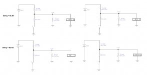
Correct. That's why I said "a valve that can be fully opened and fully closed". The effect of r-plate (in the drawing) is still the same. A larger value will result in less swing between the open and closed state. If the switch was a transistor, the circuit would perform as shown (more or less). A tube on the other hand is backwards or is working backwards from what I understand of this circuit. If a tube becomes 'more conductive' (it's ability to shunt v-out) with a smaller r-plate then I can sort of understand why the circuit seems to work backwards but that's a variable I'm not aware of.
Attachments
Last edited:
You need to delete that extra 100k resistor ("Rload") at the output of the circuit. You are drawing a DC circuit, and that resistor is in reality isolated by a coupling capacitor. If you do that then you will see how the output voltage can be pulled right up to 300V when the switch is open (valve cut off).Correct. The effect of r-plate (in the drawing) is still the same. A larger value will result in less swing between the open and closed state.
Also bare in mind that signal swing is not the same as gain. You can vary the load on a pentode or transistor over a fairly wide limit without affecting the output swing (which is rail to rail), but the gain certainly does change.
Last edited:
You need to delete that extra 100k resistor ("Rload") at the output of the circuit. You are drawing a DC circuit, and that resistor is in reality isolated by a coupling capacitor. If you do that then you will see how the output voltage can be pulled right up to 300V when the switch is open (valve cut off).
Also bare in mind that signal swing is not the same as gain. You can vary the load on a pentode or transistor over a fairly wide limit without affecting the output swing (which is rail to rail), but the gain certainly does change.
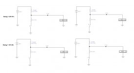
That is true but there is ALWAYS r-load. Typically 100k-1m on the next stage's grid resistor. It will effect the output level, v-out, but will not change the point I'm trying to make. The above example will always have more swing with a lower r-plate. I'll gladly change the r-load to another value for you. The result is still the same.
Yes, but it is isolated by a coupling capacitor, so it plays no part in your DC equivalent circuit. If you want to include the extra grid leak then you need to draw an AC equivalent circuit, which shows the valve as a signal generator (no battery). As it is, you are trying to mix and match AC and DC equivalents, which is why you're getting a result that contradicts reality.That is true but there is ALWAYS r-load. Typically 100k-1m on the next stage's grid resistor.
So which do you want? A way to understand an amplifier using a DC model, or an AC model?
Ok, try a 1k anode resistor. I think you'll find the output swing is only 6V, which goes against the trend you're suggesting!I'll gladly change the r-load to another value for you. The result is still the same
Last edited:
Yes, but it is isolated by a coupling capacitor, so it plays no part in your DC equivalent circuit. If you want to include the extra grid leak then you need to draw an AC equivalent circuit, which shows the valve as a signal generator (no battery). As it is, you are trying to mix and match AC and DC equivalents, which is why you're getting a result that contradicts reality.
So which do you want? A way to understand an amplifier using a DC model, or an AC model?
I tried to model it using capacitor coupling r-load and replacing the switch with a transistor and using a signal generator. The software glitched and the output was >2kv. So much for emulation. I only use ewb for drawing anyways. I have yet to find an emulator that works.
I sort of understand it when I take the DC load out. The meter is still 10m but I see where it's going. This is like general electronic stuff. I must just be having a serious brain fart. 😕
Perhaps you need a resistor in series with the base of the transistor? If you feed an AC signal directly into the transistor then the SIM may well do strange things. Whatever it is, it sounds like you have simply overlooked some essential part of the circuit that the software needs to run properly.I tried to model it using capacitor coupling r-load and replacing the switch with a transistor and using a signal generator. The software glitched and the output was >2kv.
- Status
- Not open for further replies.
- Home
- Amplifiers
- Tubes / Valves
- 6L6 / 12AX7 push-pull