Interesting that the other channel is so different. Transformer splitting is very nice but in this case you only have one transformer so we can't go that route without spending some serious coin.
Is that 47K resistor soldered directly to the grid pin at the socket? If so it might be a grid stopper designed to prevent unintended oscillation.
It sure is a strange beast. As you say it is really hard to know what the original circuit was without a schematic. Have you searched for one?
I haven't analyzed the bias points etc but I really liked the second schematics adjustable PI balance. I will have to take some time to look at Ian's schematic as it is not obvious to me how the PI balance is assured.
Interesting that the other channel is so different. Transformer splitting is very nice but in this case you only have one transformer so we can't go that route without spending some serious coin.
Is that 47K resistor soldered directly to the grid pin at the socket? If so it might be a grid stopper designed to prevent unintended oscillation.
It sure is a strange beast. As you say it is really hard to know what the original circuit was without a schematic. Have you searched for one?
I haven't analyzed the bias points etc but I really liked the second schematics adjustable PI balance. I will have to take some time to look at Ian's schematic as it is not obvious to me how the PI balance is assured.
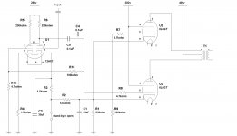
I liked the sound of the right channel (transformer split) better then the left channel. This amp wasn't necessarily a stereo amp. It was a 2-channel amp. Each channel was used for something different. Channel 1 (left) had 2 mic inputs and an aux input. Channel 2 (right) had the tremolo, reverb, and buzz, and intended for guitars. It had an aux input as well. It -could- be used as a stereo power amp but I don't think that was it's main purpose.
I've searched for a schematic and couldn't find anything. It's a National N6800 if you care to give it a shot. You may have more sources then I do.
Pin-6 and 1 are unused pins. They just used them as a connection points. Did you mean the 4.7k resistor? That is the input to pin-5.
This schematic should be how the amp is wired now.
Attachments
After tripple checking I fired it up. Right channel was very weak. Once I installed the missing capacitor 😀 it's up and running. This amp packs a punch. I have a lot of noise though. The input gain is VERY high. I need to figure out how to turn that down. The mids are also to sharp for my liking.
I'm going to try bypassing the first 12ax7 tone circuit and drive the signal straight to pin-2 of the second 12ax7. I bet alot of the noise is that first preamp stage.
I'm going to try bypassing the first 12ax7 tone circuit and drive the signal straight to pin-2 of the second 12ax7. I bet alot of the noise is that first preamp stage.
After tripple checking I fired it up. Right channel was very weak. Once I installed the missing capacitor 😀 it's up and running. This amp packs a punch. I have a lot of noise though. The input gain is VERY high. I need to figure out how to turn that down. The mids are also to sharp for my liking.
I'm going to try bypassing the first 12ax7 tone circuit and drive the signal straight to pin-2 of the second 12ax7. I bet alot of the noise is that first preamp stage.
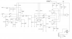
In the diagram above those two triode sections in the 12AX7 tube act a a phase splitter to transform the single ended input to a balanced signal to drive the two 6l6 tube 180 degrees out of phase. If you change something do make sure the two 6l6 grides are still driven with equal but out of phase signals
You might lower the gain by using different load resistors on the 12ax7 plates. 100K is a more common value This is a guitar amp. The simplest way to reduce gain is with voltage devides
If you are going to build a hifi staereo amp from this you will need to buy a pair of matched output transformers and do a total redesign. But you can save the power supply design and all the tubes and chassis.
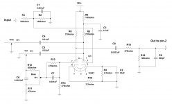
That last schematic doesn't show the preamp. There's another 12ax7 before the phase splitter. That's the circuit I'm tweaking. I haven't made any changes to the phase splitter. The tone and volume controls are in between the preamp and phase splitter and are the cause of much of the noise problem I have. Turning the bass up, for example, adds a ton of noise. I don't have a lot of hum but I have alot of buzzing that sounds like an open line in.
Were you suggesting an ultra linear transformer to replace what I have now?
Wouldn't lowering the resistor raise the output? I would think the tube could push more power if more is made available at the expense of having to dissipate higher plate currents.
Last edited:
Does the input tube in your above schematic for the phase splitter have a grid resistor? Also, if you have to much gain, try paralleling the preamplifiers tube halves and running a 100k plate resistor. Cascade the tone control between that and the phase splitter, and move your volume control to the input to the preamp.
The above schematic is the preamp. It has a 100k on the output to pin-2 of the phase splitter so, yes?
This is how I have 2 channels wired now. I'm 98% sure I have everything right. For everything else there's Mastercard (to buy the parts you blow) 😀
Attachments
I forgot to note that one output from the opt is grounded. If I tried some feedback, it would go to pin-8 of the preamp right?
If I wanted more range for the bass control, would I increase the .0033uf cap or change the 580k and 47k resistors?
If I wanted more range for the bass control, would I increase the .0033uf cap or change the 580k and 47k resistors?
Not sure on the tone control, but for kicks, I'd run a 10k resistor from your positive speaker output to pin 8 of your input tube, see how the feedback changes the sound characteristics and gain.
Not sure on the tone control, but for kicks, I'd run a 10k resistor from your positive speaker output to pin 8 of your input tube, see how the feedback changes the sound characteristics and gain.
I see how this bass control works. The .0033 is a high pass and if the pot is towards the 580k there's "less highpass" or more bass. Lowering the 580k gives much better low end.
The phase of the output transformer is important isn't it? I wouldn't want to make an oscillator and fry speakers. 🙁
I haven't tried the feedback suggestion yet. What is the purpose of it? From what I understand, feedback is used to control the gain of an amplifier.
This amp has been a big playground for me to learn how things work. For one, 90% of my noise was from the preamp so I ditched the entire pre/tone stage and drove my CD player right into pin-2 of the driver tube, with a pot for volume of course. WOW! 😀 Only a very slight hum can be heard a few inches from the cone. No other audible noise. I don't think I've ever heard an amp that didn't make "idle noise". That constant hiss from the tweeter? Hate that. As far as output power goes, it has plenty of that. I have some el-cheapo bookshelf speakers rated for "100w" and I can hear cone flex from the 6" woofer in them. Good thing they're just bench test speakers.
I'm going to design my own pre-amp/tone control and hopefully create something more "hifi worthy" then National's design. Their pre-amp had a voltage divider on both the front and rear ends and adjusting the values did little for the overall gain of it. I'm going to go with the suggestion of parallel triodes from a 12ax7. I really only need it 1:1 to keep the tone control stable with varying input loads.
Feedback might be good to tame down the amp and "tighten up" things, and decrease gain slightly. Can you easily drive the amp into clipping?
Feedback might be good to tame down the amp and "tighten up" things, and decrease gain slightly. Can you easily drive the amp into clipping?
Does "tightening things up" have a compression-like effect? The way it is now I actually like how the instruments pop out at me while listening. Transient response I believe it's called? Or maybe just attack.
"Can you easily drive the amp into clipping?"
Using my CD players line-level into pin-2? Easily. I have a 100k gate resistor from pin-2 to ground. Also a .001 parallel with that resistor. From the volume (500k) is a 100k series resistor to pin-2. So even with a 1/2 divider, I can drive it to clip with only the paraphase driver. The first thing I notice is the high-end start to roll off (OPT saturation?) then the bass gets flabby and distorted. Clipping I would assume. I'm sure my neighbors love me by now. 🙄
I now completely understand how the paraphase works. The 12ax7 paraphase driver has 2 (A and B) triodes. The input audio feeds triode A where it gets inverted. The inverted signal from triode A feeds one output tube. It also gets fed into triode B where it gets inverted again back into phase with the audio. The in-phase signal then drives the other output tube. One is on while the other is off. Push-pull. I had to stare at the schematic awhile before it clicked. I've never built anything with tubes before but when I realised they work like a transistor voltage amplifier it all made sense. 😀
Last edited:
I made a pre-amp using parallel triodes of another 12ax7. Tone control is in between that and the paraphase driver. Trebble is a cap to ground through the trebble pot and bass is a series cap with the bass pot parallel with that cap. It's as simple as it gets. I'm tuning everything by ear and once I like it I'll throw it on the scope and see how bad it really is.
Schematic soon.
Schematic soon.
I will have to take some time to look at Ian's schematic as it is not obvious to me how the PI balance is assured.
The grid of the 2nd 12AX7 stage is connected to the junction of the two 330K resistors, which is a virtual ground point, since the two resistors form a voltage divider across the two out-of-phase output signals.
If the two out-of-phase output signals do not exactly match each other (in magnitude with opposite polarity) then the grid of the 2nd stage will get an error signal from the junction of the two 330K resistors to correct the imbalance, forcing the 2nd stage to mirror the first stage.
I don't know if it would sound any better than what Lazzer is doing now. Good to hear you're pretty happy with the amp Lazzer, guess you've been bitten by the bug. Great job you've done on that amp.
Global negative feedback is intended to keep the frequency response flat and reduce distortion. GNFB requires more gain which causes more distortion so that we can then cancel out some distortion, plus it adds possible instability. My ears prefer no GNFB. I'm just a newb so what would I know.
I'm having some distortion problems that weren't apparent the first few time I was listening. Could be a new problem. I have a CD with a varity of music and it was the Eagle's Sad Cafe's saxophone that pointed it out for me. Everything sounded fine until that sax kicked in. It sounded like the sax was running through an overdriven guitar amp. Everything else sounded ok though. Go figure.
On the bright side, pun intended, my tone controls are working well.
I still haven't re-capped the amp yet. I'm using 42yr old components! 😀 But like I said, this is a learning experience to better understand tube amp design. I've learned that it's fairly forgiving. Seems like tubes "just work" and being off a bit doesn't greatly effect the sound. Either that or I'm doing a good job of keeping the design in the ballpark.
I still have to much gain on the parallel triode preamp. I may need some help with it. What I need is to buffer the input not amplify it. The paraphase has enough gain that a preamp isn't needed but if I want tone control, without effecting the input impedance and capacitance, I need to add another tube at the input. The tone controls would go between that tube and the driver.
What about just a cathode follower as the first tube input stage, it will give no gain but will be a low impedance source for the tone stage.
Regarding GNFB I forgot to mention another advantage that it lowers the output imedance of the amp. There is a good thread on GNFB here
http://www.diyaudio.com/forums/tubes-valves/171727-global-negative-feedback-schematic.html
Regarding GNFB I forgot to mention another advantage that it lowers the output imedance of the amp. There is a good thread on GNFB here
http://www.diyaudio.com/forums/tubes-valves/171727-global-negative-feedback-schematic.html
Does "tightening things up" have a compression-like effect? The way it is now I actually like how the instruments pop out at me while listening. Transient response I believe it's called? Or maybe just attack.
Feedback is kind of a slippery thing. Tightening things up in this context probably refers to tightening the bass response and some of the distortions inherent in pentode mode output distortion. The problem is that one of the unintended consequences can be sucking some of the life (or dynamics) out of the music if it is not done right.
Unfortunately if you are going to run pentode mode you almost have to have some type of feedback. Global (not including the tone control section) is the normal approach but there are some other options all of which have pros and cons. GNFB including the output transformer helps to linearize less than ideal transformers but is more susceptible to instabilities (oscillation) even outside of the audio band due to the transformers reactance. Having access to an oscilloscope helps a lot with this. Another problem is that if the response of the transformer is rather poor to begin with the correction signals applied via. feedback can be quite large and can drive either the OPT or other components into an overload condition.
Another approach is to use either local feedback or global that does not include the transformer. You can't compensate for transformer performance this way but you can deal with the nonlinearities and high Zout of the output tubes this way which will help wit overall distortion and bass response (tightness). If you have UL taps on the OPTs the UL mode connection provides some local feedback (or at least something that acts a lot like it). Triode connection also provides local feedback but reduces output power substantially. That may not be a problem if you have plenty of power (not gain but power) already.
Another type of local feedback that I am planning on trying in a couple of projects that I am now working on is the plate to plate feedback where a resistor between the output tube plate and the driver plate provides feedback essentially to the output tube grid. The idea is to linearize the output stage and reduce effective Zout. I am not sure but in your case you might have to insert a separate driver stage after the PI to accept the feedback as the impedance seen by the feedback resistor might otherwise be different in the two phases causing a different amount of feedback on each side. Again this is just my gut feeling.
Last edited:
- Status
- Not open for further replies.
- Home
- Amplifiers
- Tubes / Valves
- 6L6 / 12AX7 push-pull