Perhaps you need a resistor in series with the base of the transistor? If you feed an AC signal directly into the transistor then the SIM may well do strange things. Whatever it is, it sounds like you have simply overlooked some essential part of the circuit that the software needs to run properly.
Actually I do seem to remember having to stick a 1k to the base to make it work in the past. Like I said I don't use it for emulation.
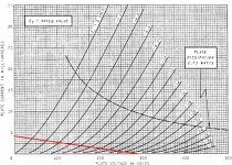
It seems the important fact I'm missing is the tube having a large plate resistance when it's "on". I was looking at the cathode resistor as the (only?) resistance to ground when the tube is conducting. I needed to see this in terms of the tubes "inability to conduct" to see that a small plate resistor keeps the output voltage higher or closer to B+. The tube can't pull it as low with it's high internal resistance.
Am I close in saying that if I reduce the plate resistor 50% that I also reduce the output swing 50% as well?
Last edited:
Best I can show for now. My camera does this NO justice at all. It killed the brilliance. Oh well. At least you hear hear -something-
YouTube - 6L6GC PP into wharfedale diamond 8.1
YouTube - 6L6GC PP into wharfedale diamond 8.1
Well there's nothing dangerous about it. Only you can decide whether you're happy with the sound!Good or bad?
Well there's nothing dangerous about it. Only you can decide whether you're happy with the sound!
It sounds good so far but if I'm running my tubes at 'less then ideal' operating points then I feel it should be adjusted. I may not know what I'm missing. I really like how the buffer>tonestack>gain preamp is working out. The bass and trebble controls are boosting/cutting at frequencies I find pleasant. I did tweak the tone circuit though. The bass control cutoff frequency was a little to low.
Playback through the little wharfedales I have to nudge the bass and trebble up a little bit. About 1:00. I'm sure both tone controls would be closer to 12 (flat) with better speakers.
The new tone values will show in a final schematic. Then the build begins.
I may have made a mistake in my schematic. Which side of the 12ax7 phase inverter gets the bypass cap?
EDIT - Yup I drew it wrong. The bypass cap goes on pin-3 not 8
EDIT - Yup I drew it wrong. The bypass cap goes on pin-3 not 8
Last edited:
The potential divider that feeds the 'slave' side has a gain of 4.7/(100+4.7) = 0.045, so you want that triode to have a gain of 1/0.045 = 22.3.I may have made a mistake in my schematic. Which side of the 12ax7 phase inverter gets the bypass cap?
As shown, the gain is about 50, so you have a very unbalanced stage!
Hence the bypass cap should be on the other triode.
The potential divider that feeds the 'slave' side has a gain of 4.7/(100+4.7) = 0.045, so you want that triode to have a gain of 1/0.045 = 22.3.
As shown, the gain is about 50, so you have a very unbalanced stage!
Hence the bypass cap should be on the other triode.
I checked. It is. I copied it to schematic wrong that's all.
I need some help figuring out bias. Both output cathodes are connected together then through a 240ohm to ground. A 6L6GC is 23w. 2 is 46w. I have 400v B+. 46w/400v=.115a. I should have 27.6v across 240ohm when .115a is flowing through it. Is that right so far?
What do I wan't for idle current?
I'm measuring about 29.3v across that 240ohm. That's .122 or about 60ma each tube. I don't know how to account for screen current.
What do I wan't for idle current?
I'm measuring about 29.3v across that 240ohm. That's .122 or about 60ma each tube. I don't know how to account for screen current.
Last edited:
EDIT - They are 250ohm not 240ohm. I have no idea why I didn't use a custom resistor in the software. I used the closest value at 240ohm. Anyways... At 250ohm I have 29.3v across it which is 0.1172a. That's a little better. Sound ok for a 6L6GC?
I need some help figuring out bias. Both output cathodes are connected together then through a 240ohm to ground. A 6L6GC is 23w. 2 is 46w. I have 400v B+. 46w/400v=.115a. I should have 27.6v across 240ohm when .115a is flowing through it. Is that right so far?
What do I wan't for idle current?
I'm measuring about 29.3v across that 240ohm. That's .122 or about 60ma each tube. I don't know how to account for screen current.
Looks correct to me (neglecting screen current)..........duncan's amp tube data lists 6L6GC anode dissipation at 30W, so it looks like you are driving the tubes well under thier max ratings..my triode EL34's are running at 400V/60ma each with no problems.
Looks correct to me (neglecting screen current)..........duncan's amp tube data lists 6L6GC anode dissipation at 30W, so it looks like you are driving the tubes well under thier max ratings..my triode EL34's are running at 400V/60ma each with no problems.
Ok thanks. Just making sure I'm going about this the right way.
Anyone hear about driving screens with a "virtual UL" resistor? Any advantage to that over the DC supply to the screens?
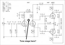
Can a circuit like the Williamson (see attached) be able to drive a tone stack and retain enough gain to get 30-40w from 6L6GC output tubes?
What's up with multiple stage filter on the input?
What's the swing on the input to this amp? In general no. The tone stack needs to be driven be a low impedance like a cathode follower and then you need a gain stage to recover. So you may need another dual triode. Of course there are different tone stack designs. Are you talking about three controls (bass, mid and treb.) or just one "tone" control that shunts the highs.
Where to put it? I'd say in the "pre amp" ahead of your entire schematic. The volume control can go in there too and maybe even a "balance" control.
THis is the kind of question that is easy to answer with a Spice model. The software is zero cost so is worth having
The reason I didn't put the tone stack before the preamp was because I figured the input load isn't constant that way. I only have 2 tone controls. Bass and treble.
Just to update. This is how it's wired now (give or take a few values). The volume was changed to 500k for example. It's a cathode follower to drive the tone stage and then a gain stage after it into the PI.
Attachments

Last edited:
- Status
- Not open for further replies.
- Home
- Amplifiers
- Tubes / Valves
- 6L6 / 12AX7 push-pull