I have another question. It's common to see a power supply with voltages tapped at poins along a string of series resistors R1 and R2.
In the top schematic:
The power stage draws current at point A, this also causes a voltage drop at point B. If B is powering the preamp/PI then wouldn't that cause unwanted voltage sag in the audio and drive signals?
In the bottom schematic:
The preamp sources it's voltage directly from B+. Other then some sag in the power transformer, wouldn't this create a more stable voltage to the preamp/PI?
I already know it would. I'm just wondering why so many amplifier designs use the top schematic with the series resistors.
Attachments
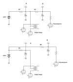
The series of RC networks (RCRC in your schematic) drops the voltage for subsequent tubes, with a gain in reduced ripple.
Each additional RC stage filters the DC and cuts the amount of AC ripple remaining from rectification.
Pre-amp stages are more sensitive to this ripple and tend to amplify it (as a general rule, there are some tube topologies that have good PSRR {power supply rejection ratio} and are not as subject to this.).
The series of RC networks (RCRC in your schematic) drops the voltage for subsequent tubes, with a gain in reduced ripple.
Each additional RC stage filters the DC and cuts the amount of AC ripple remaining from rectification.
Pre-amp stages are more sensitive to this ripple and tend to amplify it (as a general rule, there are some tube topologies that have good PSRR {power supply rejection ratio} and are not as subject to this.).
So could the preamp/driver still get it's power from B+ but then have it's own set of RCRC better tuned to reduce noise? I'm just wondering what the effects of voltage fluctuation has on the preamp/driver. The "audio ripple" introduced into the supply has to have some effect on the preamp/driver. A form of feedback really.
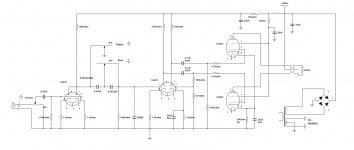
Here's where I'm at so far. It needs some adjusting (less gain in the preamp) but doesn't sound half bad. It's getting late. I hope I got it right. 🙂

Attachments
Last edited:
Lingwendil has suggested earlier in this thread (post #40) to reduce the size of the anode resistors of the phase splitter to get more drive current before distortion sets in, that would also reduce the gain. Maybe 100K anode resistors for the phase splitters would be worth trying. The 10uF cap after the rectifier is small by "todays" standards, 47uF seems to be a common minimum these days. The bypass capacitors on the cathodes seem to be designed to limit bandwidth for musical instruments. Have you seen the valvewizard site, it is an easy read.
Lingwendil has suggested earlier in this thread (post #40) to reduce the size of the anode resistors of the phase splitter to get more drive current before distortion sets in, that would also reduce the gain. Maybe 100K anode resistors for the phase splitters would be worth trying. The 10uF cap after the rectifier is small by "todays" standards, 47uF seems to be a common minimum these days. The bypass capacitors on the cathodes seem to be designed to limit bandwidth for musical instruments. Have you seen the valvewizard site, it is an easy read.
That and some feedback. I haven't got to those yet. The anode resistors are easy enough to try first. Which cathode capacitors are you speaking of? Everything before pin-2 of the PI I built. The power supply capacitors are three 3in1 cans of 10 10 and 20uf. I tried splitting off a 10uf and putting a choke in series before the others. It didn't do anything and I've taken the choke out.
Take a look at that first parallel triode that I'm using for a preamp. How do I lower it's gain without just dividing it down? Every time I put a resistor anywhere in series with the audio signal, the high end suffers. That's why you dont see any series resistors besides the pot and the PI divider.
I don't think I'm having any distortion problems at all. The CD I was playing (Eagles) was a burned copy so I could keep one in the car. For $hits and giggles I ripped another copy and opened it in a wave editor and sure enough, the tips of the wave were clipped in the same part of the song that I heard distorting. Now here's the interesting thing. I didn't hear it until I listened to that CD through this amp. Darn it it's to good! 😀
Everyone's input has been great. It motivates me to keep pursuing the build and try new things. So far so good. I liked where it was going enough to build the second channel. I'll give it a good stereo cranking tomorrow.

I was thinking the 35uF cap on pin 3 of the 2nd 12AX7 and on the cathodes of the 6L6 might be affecting the bass response, but if it all sounds good then proly best to leave it alone. These days caps are cheap, compared to when that amp was built, and many modern designs are using much bigger caps in those positions. But in reality, the 35uF caps should be sufficient.
I wonder if it would be worth moving the volume control position to right before the PI? That way you get full signal into the 1st 12AX7 for best SNR. The first 12AX7 has a gain of around 60, the only method I know to reduce the signal is to use a voltage divider, which could be done by the pot. There are other tubes with less gain but I think you want to stick with what you have. Better still, if you can live without tone controls, and put the source signal straight into the PI...
Glad you sussed out the distorted sax, your amp must be pretty decent if you can hear the details, I love tube amps for their detail. The amount of distortion on some modern CD's is just plain wrong, are we going forwards or backwards?
I wonder if it would be worth moving the volume control position to right before the PI? That way you get full signal into the 1st 12AX7 for best SNR. The first 12AX7 has a gain of around 60, the only method I know to reduce the signal is to use a voltage divider, which could be done by the pot. There are other tubes with less gain but I think you want to stick with what you have. Better still, if you can live without tone controls, and put the source signal straight into the PI...
My honest suggestions are to reduce the phase inverters' anode resistors to 100k, and either implement a small amount of feedback, or try a 12AT7 in the first position in the amp. The volume control between the input and inverter might be worth trying, but I've tried this on a few 12AX7 designs, and with some sources you can overdrive the first stage this way.
I was thinking the 35uF cap on pin 3 of the 2nd 12AX7 and on the cathodes of the 6L6 might be affecting the bass response
Isn't that part of the PI? Assuming National has it balanced correctly, wouldn't making a change like that unbalance the PI?
Glad you sussed out the distorted sax, your amp must be pretty decent if you can hear the details, I love tube amps for their detail. The amount of distortion on some modern CD's is just plain wrong, are we going forwards or backwards?
If you think about it. CDs are aweful. If there's 44k bits per second how can you make a sine wave at say 11khz? 44k/11k is 4 bits. How can you draw a circle with 4 pionts? interpolation=fail. I think CD players are making more data using interpolation then is actually recorded to the CD. You know what would have been great? Analog modulation of the laser to burn the CD like a record. Playing it back with a laser of course. I don't think there's any better way to record/playback an analog signal.
My honest suggestions are to reduce the phase inverters' anode resistors to 100k, and either implement a small amount of feedback, or try a 12AT7 in the first position in the amp. The volume control between the input and inverter might be worth trying, but I've tried this on a few 12AX7 designs, and with some sources you can overdrive the first stage this way.
I tried reducing those resistors to 125k (I used another 250k in parallel) and managed to damage one side of my PI tube. It could have been failing and that did it in? I tried some feedback and all I can say is I'm glad my tweeters survived. 🙁 Made a great 18khz oscillator.
I'm fairly happy with it's sound quality so far other then the gain. I'll try the volume between the preamp and PI and see how that works. I'm sure that will get rid of the idle hiss at very low volumes because without the preamp connected to the PI it's silent except for some power supply hum. The caps are old and small and I'm sure it'll clean right up with some better caps.
I replaced the diodes with new ones, with less voltage drop, but this increased a very faint buzz from the left channel. I'm not 100% sure why only that channel was doing it other then each channel has it's own PS capacitor. One may be weaker then the other. What I did that significantly helped with that power supply noise was put a choke in series right after the rectifier and before the capacitors. The buzz is eliminated.
My opinion is that my OPTs are well suited for the 6L6GCs. The 12AX7 PI has enough power to drive the 6L6s to fairly loud levels. It can get uncomfortablly loud before distortion sets in. The PI and output stages are silent as far as I'm concerned. I'm sure something might show on the scope but with a tweeter to my ear I hear nothing. There is that soft faint hum from the woofer but I'm sure thats just 42yr old capacitors. I'll soon be building the chassis and I REALLY like how this one retail amp looks but for the life of me I can't find a picture of it. The output tubes are end to end inside a round cage and laid horizontally from from to back on the sides of the chassis. There's a crescent shaped wood panel in front. Anyone seen it?
Last edited:
I tried reducing those resistors to 125k (I used another 250k in parallel) and managed to damage one side of my PI tube. It could have been failing and that did it in? I tried some feedback and all I can say is I'm glad my tweeters survived. 🙁 Made a great 18khz oscillator.
Did you try reversing the transformers' secondary leads?
Did you try reversing the transformers' secondary leads?
No I didn't get to that. I've been focusing on the power supply and noise levels.
I've been meaning to ask. Are there recomended voltages for the output's control grids? I've removed a total of 6 12ax7s from this amp and I bet the voltages have crept up a bit. And those 120ohm cathode resistors get very hot.
Last edited:
I was thinking the 35uF cap on pin 3 of the 2nd 12AX7 and on the cathodes of the 6L6 might be affecting the bass response
The I tried removing the 35uf on the 6L6s and couldn't detect any change. Maybe at higher volumes? I tried reducing the cathode resistor from 270ohm to 160ohm and reduced the onset of distortion quite a bit. I've seen other amps connecting it straight to ground. What would be a safe value here? Or should I stick with the 270ohm and put in a larger capacitor?
I wish I could edit posts anytime then keep adding more. -frustrated-
Does the B+ to the preamp effect the noise level? I'm at 287v with 100k to the plate, 1.1k from the cathode to ground and a .01uf parallel with the 1.1k to brighten up the highs. Decreasing the plate resistor will lower the gain. Will lowering the B+ also help reduce the gain and noise? Maybe 150v B+, 50k plate, 500ohm cathode?
Does the B+ to the preamp effect the noise level? I'm at 287v with 100k to the plate, 1.1k from the cathode to ground and a .01uf parallel with the 1.1k to brighten up the highs. Decreasing the plate resistor will lower the gain. Will lowering the B+ also help reduce the gain and noise? Maybe 150v B+, 50k plate, 500ohm cathode?
I tried reducing the cathode resistor from 270ohm to 160ohm and reduced the onset of distortion quite a bit. I've seen other amps connecting it straight to ground. What would be a safe value here?
Are you referring to the 6L6 cathode resistor?
Maybe Figure 14 here will help with gain problems.
Yes I am. When I start pushing the amp hard I can hear the bass begin garble things up. I noted this position on the volume knob. I dropped the cathode resistor to a 160ohm an played the same song at the same volume position and there was little to no distortion. The cathode capacitor doesn't have any effect at low volume but as the amp is turned up it has a greater effect of reducing distortion then without it. Another 35uf in parallel with the first had about the same effect as lowering the resistor but it seemed that deap bass suffered as a result. Tone wise, at high volume, it sounds better with 160ohm/35uf then with 270/70uf. Make sense?
Thanks for the tone schematics! That's exactly what I'm trying to accomplish. Figure 14 -They used a cathode follower like a buffer to drive the tone stack then a voltage amp to get the gain back up? Looks good. But there's one problem. All those components! 😱 It's just asking to make noise. I think I'll build one and try it though. It's easy to do with this 2-channel sand box I have here. I can make a change to one channel and immediately compare it to the other channel. 😀
I needs me some a them there capasa-taters with a side a zisters.
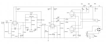
I built this tone circuit from the link Ian sent me. I built the first triode cathode follower and ran that straight into my PI. Much less noise compared to the 12ax7 parallel preamp I had which I did try as a single triode which sounded the same either way. Once I listened awhile, and was convinced this cathode follower was working, I added the tone stack and the second half of the 12ax7. Well, welcome back noise! And more so then I had before. The input to the second triode hears any interference from every component, lead, wire, and pot in the tone circuit. I'm going to try moving the volume pot over to the second triode's output. At least that should stop the idle noise and bring up the s/n ratio. I know the PI and output stages are silent.

Attachments
My signal path is now straight into the circuit above and the output is across a 50k pot with the wiper to pin-2 of the PI. Good results so far. Signal to noise is much better. Bass responce is excellent.
Q1: Which filament option is best and why? Size/Weight/Cost not a factor.
1-Filament power from main power transformer. AC
2-Filament power from main power transformer. Rectified and filtered DC
2-Separate filament transformer. AC
3-Separate filament transformer. Rectified and filtered DC
Q2: Is a cathode follower inverting?
Q3: In my schematic... Adjusting the volume changes the PIs grid path to ground. Does this effect tone or quality?
Q4: Am I running way to much current on my first stage cathode follower?
How the schematic look otherwise? It sounds good and gets pretty loud before distortion sets in but it feel like there's alot more volume left after the onset of distortion. The mid-bass is the first thing to distort. High end and bass drums seems ok. Lowering the 6L6 cathode resistor from 240 to 100ohms helps but it seems like that's effecting the high end at normal volume levels. If I keep it at 240ohms but raise the capacitor from 68uf to 100uf it seems to give me the best of both worlds.
And yes, I still have to try feedback. Could this help? I drive it right into pin-8 of the first 12ax7 correct? I can't imagine why I'd want feedback running through the tone stage so it should enter after the first triode. I still have to try lowering the plate resistors to the PI but I'm worried this might reduce the gain.
Attachments
Last edited:
- Status
- Not open for further replies.
- Home
- Amplifiers
- Tubes / Valves
- 6L6 / 12AX7 push-pull