Looks similar to this Korean 6JS6:
One 6JS6 C Sylvania Tube N O s Tested | eBay
But I only see 31JS6 listed for higher heater V. There is 26LX6, but it draws 0.6 A for heater.
If the getter flashes are still there, you might be able to bake the tube to get the gas reduced.
One 6JS6 C Sylvania Tube N O s Tested | eBay
But I only see 31JS6 listed for higher heater V. There is 26LX6, but it draws 0.6 A for heater.
If the getter flashes are still there, you might be able to bake the tube to get the gas reduced.
Last edited:
Really is very similar in appearence.Looks similar to this Korean 6JS6:
One 6JS6 C Sylvania Tube N O s Tested | eBay
But I only see 31JS6 listed for higher heater V. There is 26LX6, but it draws 0.6 A for heater.
If the getter flashes are still there, you might be able to bake the tube to get the gas reduced.
About baking:
http://www.diyaudio.com/forums/tubes-valves/231203-baking-tubes-procedure-help.html
Like in GIMP explanation? Interesting opportunity to know if it works...
Anyway, 14 minutes with 26V/450mA at filament and some screen+plate dissipation makes the tube very hot and the internal gas only grow.
In most gaseous PL509 I have left with some plate dissipation, the gas starting to reduce with less than 10 minutes, so I have low spectations... but curiosity at same time, so soon I try that.
"Like in GIMP explanation?"
Yes. Would be interesting to see if that works at least.
Even so, the leak that let the gas in will eventually repeat. Question of how long that takes. Then its time for "modding" the tube with a hammer (tube in a safety bag). Can take pics of the internals. Or give it the Tubelab treatment. 😱
Yes. Would be interesting to see if that works at least.
Even so, the leak that let the gas in will eventually repeat. Question of how long that takes. Then its time for "modding" the tube with a hammer (tube in a safety bag). Can take pics of the internals. Or give it the Tubelab treatment. 😱
Perfect! If baking don't works (fail) I promise some tube dissection here in DIYA...
And thanks all for the tips!
And thanks all for the tips!
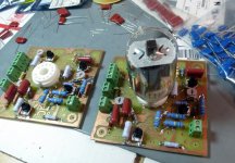
This is a picture of the first PC board I cooked up in the new location. Yes, there is a 6GE5 stuck in one of the boards. I made it just for you guys.........and the 28 other tubes that will work in it.
A single board can be used for SE, or a pair for P-P. 6GE5 triode testing should be a piece of cake. It will be Tuesday before the Mouser box brings me the stuff I need to finish populating it all, but there are a few things I can test soon. Stay tuned.
A single board can be used for SE, or a pair for P-P. 6GE5 triode testing should be a piece of cake. It will be Tuesday before the Mouser box brings me the stuff I need to finish populating it all, but there are a few things I can test soon. Stay tuned.
Attachments
AWWWWW YISSSSSSSS
I need to learn how to make nice PCB's like that.
Hahaha I dig the star trek nod btw! To explore strange new tubes!
Too late here for me to give a good evaluation. I will check back when I am fully awake. Happy Day!
I need to learn how to make nice PCB's like that.
Hahaha I dig the star trek nod btw! To explore strange new tubes!
Too late here for me to give a good evaluation. I will check back when I am fully awake. Happy Day!
Last edited:
I need to learn how to make nice PCB's like that.
They are not so nice, but functional PC boards. Each had a few broken traces, but these were the first boards that I have made in a couple of years. I jumped the broken spots with wire and moved on. I often make these for prototypes because they are fairly cheap and quick. Often there are no bad spots, but sometimes there are a few. I have been told that these home cooked PC boards will eventually fall apart, so don't bother....BS.
Boards that I made in the 60's and early 70's on brown phenolic have indeed come apart. Everything I have made since G10 / FR4 (epoxy fiberglass) was invented is still functional despite 40 years or so in Florida humidity. My personal TSE amp (Tubelab amp #001) still has the has the home cooked proto PCB in it. It is over 10 years old and has 85 year old output tubes!
There are two ways to make these. The easiest way is the toner transfer method. That is what I did on these boards. You design and layout a PC board in your computer. I use Eagle, but there is freeware like Design Spark available.
Print it on a "toner transfer sheet" (some people use old magazine pages) using a laser printer, then iron it onto a piece of copper clad blank board, then soak in water. The water soak removes the paper transfer sheet, leaving the toner image on the board. Etch the board in ferric chloride (still available at Radio Shack......if you can find a Radio Shack.
There are dozens of Youtube videos demonstrating this, but I will make one once I set up for video.
Super simple one-off PC boards can be made by drawing the pattern directly onto copper clad board with a Sharpie, then etching.
There is a photographic method that involves using pre sensitized board at about $10 for a 6 X 9 inch piece, and it does result in a higher quality board with better resolution, but I only use it when working with small SMD stuff.
I have been buying the dual layer standard eurocard size (160mm x 100mm) blank pcb boards from radioshack. I also have the ferric chloride I got at the shack. About a year ago or so when I heard radioshack was going out of business I asked the guy at our local one what was up and he said they are going to remain in business so that's good.
I have not tried to directly draw on the boards with a sharpie method. I have tried the toner transfer method for a power supply board. I didn't use old magazine paper although I heard this works great. The stuff I used was from staples and was hard to get off the board after I ironed it on. I heard the magazine paper is easier to get off so I think I will try that next. I too use eagle but only the freeware which limits me to half a eurocard size (80mm x 100mm). I think my problem is I am not that good at doing the layout and trace size etc.... I used the automated routing method and that was okay but the traces were small. I guess like anything if I keep trying I will get better. I personally like P2P better but I would like to still be able to make functional pcb's that have a nice thought out layout.
I look forward to your parts arriving next week and more testing with the 6GE5 and other tubes. I have been side tracked on my progress with the 6HJ5 amps, I should be back at em this weekend.
Pair 3K 10 Watt SE Transcendar Audio Output Transformers for Amp 8 Ohm | eBay
I need some iron. Another fellow member on here said he ordered from Edcor and got his iron in TWO WEEKS!!!! Last time I had to wait two months. So instead of waiting I was thinking of trying some transcendar iron. Any thoughts? Two weeks isn't bad and if I can get Edcor in two weeks time I can live with that but I really don't want to wait two months so I might pull the trigger on the Transcendar's if people have had good results with them. The Edcor is less than half the price of the Transcendar's https://edcorusa.com/gxse10-8-2_5k
I used these toner transfer method (laser monochrome printer) successfully, too. I can confirm that the use of magazine pages brings excellent results, provided they do not contain large black areas on the page (ex .: advertisements with black background), so the plain text pages are the most suitable. The black parts of the magazine do not transfer toner right to PCB, or are transferred together and the entire board is flooded with "toner". I used a press to stamp t-shirts to make my PCBs, this in my previous job. I am in the new job in the IT field and since I made few PCBs for my own use, I make them with the pen (that old method😀).
It's been five years since I've used this toner process, and to see the work of Tubelab brings me good memories ...
I've told some people modify laser printers for direct printing on copper, but I don't now if it works or if is reliable.
By the way, those who say that PCB does not works or is ugly with valves, I disagree! I find valve beautiful on a PCB.
By the way, those who say that PCB does not works or is ugly with valves, I disagree! I find valve beautiful on a PCB.
I have to agree with you on this. I like point to point only because I find it easier to swap parts in and out for modding or servicing. But I too really like the look of tubes on a PCB. I really want to work on getting a nice linear layout for a passive RIAA phono preamp I am making but I ended up settling on point to point because my PCB making skills are not up to snuff.
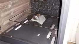
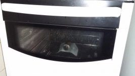
baking tubes?!
Honey, what we will have for dinner today? 😀😀
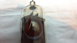
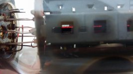
This works partially. Visually the getter was working a little, but gas remains at somewhat lower quantity (ops, I don't have the BEFORE photo, thanks to my haste 😡 ). These tube has very low and falling emission, and only works with pulse operation like µTracer, at DC this tube barely pass 50mA now even if connected as diode with 350V😕! (even the µTracer results become a little poorer...)
The internal photo without gas is without DC applied.
The internal photo with visible bluish-white gas is with DC applied.
Honey, what we will have for dinner today? 😀😀
This works partially. Visually the getter was working a little, but gas remains at somewhat lower quantity (ops, I don't have the BEFORE photo, thanks to my haste 😡 ). These tube has very low and falling emission, and only works with pulse operation like µTracer, at DC this tube barely pass 50mA now even if connected as diode with 350V😕! (even the µTracer results become a little poorer...)
The internal photo without gas is without DC applied.
The internal photo with visible bluish-white gas is with DC applied.
Attachments

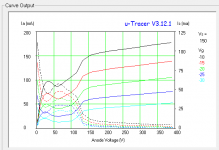
The µTracer results...
Next time... hammer it!
(probably I need to post it at baking topic...)
Alas, before I measured higher current (the almost 300mA total cathode current at DC) maybe due to gas!
Next time... hammer it!
(probably I need to post it at baking topic...)
Alas, before I measured higher current (the almost 300mA total cathode current at DC) maybe due to gas!
Attachments
Last edited:
I admire your efforts at resurrection, but even Frankenstein wouldn't be able to bring back life to that one.....
Time to give it a decent burial!
Time to give it a decent burial!
I used the automated routing method and that was okay but the traces were small.
I have been laying out PC boards since the 70's. Back then the PC had not yet been invented. In fact most of the boards I was making then were for SS-50 and S-100 bus "home computers". In the late 70's it was Apple II clones and TRS-80 expansion boards. We used the tape and mylar layout method that required a specialized darkroom. I started using Eagle in about 1992 with DOS version 2.6. I designed PC boards when I worked at Motorola, but they were tiny, extremely dense HDI boards for cell phones and two way radios.
All my tube PC boards use the same routing rules, 50 mil runners on 50 mil spacing. Every pad and via is oversized. I edited the parts libraries and increased the pad sizes as much as practical on all the parts. I sell my boards to builders of all skill levels. Many have never built a PC board before, and large pads are harder to rip off a board. I don't use an autorouter, they generally will make a mess of most boards. The fancy auto routers built into $20K per user tools like Mentor Graphics or Cadence are better, but still mess up RF designs. They are good for dense digital designs.
I might pull the trigger on the Transcendar's if people have had good results with them.
Maybe 8 years ago I bought a pair of Transcendar SE OPT's on Ebay. They were specifically made for a 300B amp, which is what I was building. I liked them a lot, enough to send him an email asking if he had more. He replied that he was a retired transformer designer selling off his leftover stock. I bought all of those 300B transformers. Gerry started making audio transformers in his spare time and selling them on Ebay. I have not tried any of those newer transformers, but reports are very favorable.
Bad news on the test board. I found enough parts to populate the standard G1 driven pentode connection option, did so, and fired it up today.
Unfortunately there was a bright flash of light and a poor sweep tube was executed in the hot seat. Investigation revealed that I had inadvertently swapped the top and bottom layers in the layout which reversed the pinout for anything with more than two pins. The tube socket, six pots and all 4 mosfets are reversed. The miswired tube socket put 400 volts on G1.
This caused two of the mosfets and at least one tube to die. I am trying to find a way to salvage the board, but it looks like a new one needs to be made.
It's been that kind of weekend. Friday I had to fix my daughters car. We took the grandkids and their friends to the playground, where one kid left in an ambulance with a broken and mangled arm. Spent all day Saturday at the hospital while he had surgery. Two steel rods and a cast to fix it. Sunday I had to move furniture and fix my brother in laws car. This morning I blew up the board, and this afternoon we took some toys to the kid with the arm in a cast, and his cat bit me. At least my daughter fixed us all some grilled pork ribs.
Tomorrow I am going to try to swap the pots, tube socket, and mosfets to the other side of the board, replace the burnt stuff and try again.
Tomorrow I am going to try to swap the pots, tube socket, and mosfets to the other side of the board, replace the burnt stuff and try again.
I thought playgrounds were supposed to be safe. Until I ruined my shoulder on a hanging slider rail years ago. Class III whitewater kayaking is safer than those da_n places.
Some consolation: there is a new interesting tube on the ESRC $1 list. I won't spoil the fun by naming it. Its got lots of gm. Hopefully no one blurts it out, wouldn't want them all sold to the Chinese. Maybe we could call it the tube from Hell as a codename.
Some consolation: there is a new interesting tube on the ESRC $1 list. I won't spoil the fun by naming it. Its got lots of gm. Hopefully no one blurts it out, wouldn't want them all sold to the Chinese. Maybe we could call it the tube from Hell as a codename.
Last edited:
We took the grandkids and their friends to the playground, where one kid left in an ambulance with a broken and mangled arm. Spent all day Saturday at the hospital while he had surgery. Two steel rods and a cast to fix it.
Wow, that sounds nasty. Many years ago, my step-daughter had a friend over to play. They were climbing around in our walnut tree, and the friend chose a dead branch. She hit the deck and broke her arm. Of course you feel bad for the kids at the time, but they heal pretty quickly.
jeff
new interesting tube
I'm surprised that it's on there since it can often be stuck in place of another popular tube.
Until I ruined my shoulder on a hanging slider rail years ago.
UH, another "big kid" on the playground?
I know a certain 62 year old kid who was zipping back and forth on that one when the 6 year old broke his arm on the ladder to the monkey bars. He got his arm stuck between the fat bar that supports the entire structure and the thin bar that is the hand rail and fell forward when his foot slipped off. The two bars are about 10 inches apart. His arm was bent about 90 degrees. The surgeon said that his bones were still quite soft, so it was not a clean break, lots of bent parts inside his arm.
but they heal pretty quickly.
The surgeon said that the steel rods would be in his arm for about a year. The cast he has now is temporary until the stitches come out, then he gets a smaller one, about 10 days. He was however playing video games one handed yesterday.
- Status
- Not open for further replies.
- Home
- Amplifiers
- Tubes / Valves
- 6GE5 Triode