Hi Ari,
No I don't have it.
I have buit this amp following exactly the recommendations and the values of components indicated by the Borbely's pdf project.
The only thing that I have not followed is that Mr. Borbely says that P1 should be replaced by a jumper if one don't have the distorsion analyzer. I told to myself that I could mount the related components and put the jumper later if I couldn't find the way to use those components.
The result is very grate in all the senses, but only this little issue where the high frequencies of sound are less strong in comparison with other amps. The thing is that I like very much music where high frequencies are very present.
The distorsion cancellation in this project consists in modifying the values of P1, until you get the best. Of course measuring it. P1 goes from 0 to 20 KOh, so I tell to my self: what if I increase slowly and progressively, by steps of 1 KOh while listening? If it doesn't bring any result, I'll put the jumper.
I am now re-verifying all the paths, to be sure that I have not made any mistake. I'll bring here if I discover anything that makes me a doubt.
I thank you very much for your interest.
Best regards.
José
Sorry there is a mistake in my last post: P1 is 2 KOh and the increasing steps that I meant is 0.1 KOh.
José
José
Sorry José,
Maybe I asked you before : where do you live in France ?
I have a distorsion analyzer and I could also measure the frequency range, if we had a chance to meet.
Ari
Maybe I asked you before : where do you live in France ?
I have a distorsion analyzer and I could also measure the frequency range, if we had a chance to meet.
Ari
Hi Ari,
Thank you very much for your proposition. It would be with pleasure that I could meet you to show you the amp, to analyze the distortion, etc, but if I understood well, you are in Paris, and I live at 560 Kms from there; near and East of Annecy.
In fact, I don't worry too much about the distortion cancellation, since the distortion is second harmonics; what makes me not comfortable is this issue of high frequencies being less powerful than with the other amps. And contrarily, the low are really very strong. Since I like some kind of classical music where the high frequencies are often predominant,...
I am wondering if it is a matter of Voltage anywhere in the different paths of the schematics.
The question I have in mind now is: what makes, technically speaking, the high frequencies be lower or stronger?
Best Regards.
José
It's OK José.
The high frequencies become weaker if part of them ( starting from the high end) is lost before they reach their final destination.
Case #1 - If they find an inductance on their path ( in series ) some of their amplitude is kept there.
Case #2 - Also, if they find a capacitance that takes them to ground or makes a short circuit, they become weaker as well.
Case #3 - By some interaction with the valve's electrodes, the loss may be magnified ( Miller effect ).
In your case you should check:-
a) if the anode load resistor of the driver valve is too high in value . For your information, in the "Simplex" , I keep it at 10 k and below.
b) the construction of the output transformer ( or interstage, if used ).
Regarding the latter, you can start with the following check, if you have an inductance meter :-
i) measure the primary inductance, with no load at the secondary.
Suppose you find 3 Henry ( just an orientative low field figure ).
ii) make a short circuit with the secondary. Every turn of winding that is not coupled with the primary represents a loss ( and builds a sepaarate coil of its own, outside the induction of the primary to the secondary). Measure now the inductance of the primary. It gives an idea of the non productive inductance that prevents the high frequencies from reaching the secondary (case #1 above ). The higher this inductance, the higher the loss in high frequencies. It should be, ideally, less than 2 millihenry, in a good OPT.
As far as the stray capacitance is concerned, this is much more difficult to measure. You need an oscilloscope and a specific know how.
Between turns and from winding to winding a capacitor builds up and the high frequencies that are operating in the primary find their way to ground (through the secondary or the power supply line ) or with a specific short circuit that concerns the higher frequencies.
Here also the main stream of high frequency is weakened.
The use of the 6C33 allows having a satisfactory frequency range, because you need ( thanks to the low internal resistance of the valve) a lower inductance of the primary, which means less turns.
Therefore suspect N°1 is your output transformer. Which type are you using?
In order to have a pleasant consistence of the sound ( apart from other factors) the frequency range should exceed 40 kHz, in my opinion.
This is a practical result I obtain currently.
I would just like to add that extended ranges are obtained with several interleaves ( normally 4 primary layers and 3 or 4 secondary). This explains why a power or filament transformer ( one primary block and one secondary block) cannot possibly exceed 3-4 kHz ( maybe a little more in particular cases, but still much below the required high end frequencies ).
Cheers,
Ari
Congratulations, you finally finished the amplifier;
I saw your message on the forum late last night but I was very tired to write something.
Ari wrote today everything you need to know and did much better than I would have written.
P1 change the current operation of the driver, higher current, lower distortions , in the measuring points given in the schematics you must have 240v P1 increases or decreases the voltage at the point of measurement, . In the minimum position of the P1 you should have a lower voltage. When the voltage will be 240V you will have the lowest distortion
I did an experiment and i increase the operating current of the final tube at 250mA wtth 210V , the measurements show me less distortion value.
Will bee nice to have the opportunity to measure your amplifier to see how good are the output transformers.
Talk to Ari and if he has an output transformer for tests. I would say to try one you will be surprise with the result, it will be much better in my opinion
Honestly I don't like the output transformers that you have, maybe this is the problem in the high frequency register.
I am glad the you like the sound of 6C33C.it is a nice tube in my opinion.
Recent events show me that I like more SE then PP and specially this tube.
In the near future I will made a SE with GM70 and another SE with GK71. When I will finis them I will tell all of you my opinion about them comparing to 6C33C
Good luck and keep us in touch.
Best regards ...
Thanks Gabriel.
José, have a look at Polisois audio amplifiers and transformers and you will find some more information on the subject.
For any particular question please contact me via the "contact" box.
All the best,
Ari
José, have a look at Polisois audio amplifiers and transformers and you will find some more information on the subject.
For any particular question please contact me via the "contact" box.
All the best,
Ari
With pleasure Ari
Your work and information’s are appreciated.
Every body knows that the OPT is the most important object in the valve amplifier.
A good OPT give a better performance to the amplifier.
I have a friend in Romania that made me all the OPT. he has a lot of knowledge and experience in this area. So we will not buy from China something that we can made in Romania with better result.
Gabriel
Hi to you all,
I give special thanks to Ari for his excellent explanation; I will analyze point by point from what he mentioned. I will pay attention also to the OPT, but I will do it at the end of all the checkings I still intend to do.
Gabriel, I am glad to hear from you. The feed-back you have allways given has helped me very much in my project; I've been lucky that you started before me and I could follow your steps to build my amp.
The explanation you're giving in your last post about voltage, and particularly the 240V makes me another worry, since I have discovered today that I am having a problem of over-voltage in the driver's stage.
In fact, I have replaced the R5 from the power supply by a self-inductance of 5H / 50 Ohm, and the voltage did not decrease enough: I have made a check all the way the different paths and, for the 6c33c everything is perfect, but for the drivers I get 401V where it should be 380V and, of course the rest of the voltage checking points over this entry point have aroud 40V more than it should be. Not mention the point where it should be 240V !! It appears that I measured 337V.
I cannot nderstand how this could happen since the values of the resistors are correct.
I have already prepared a resistor to solder tomorrow in series and decrease the overall voltage until I get the correct values.
Do you think that this could be one of the eventual reasons of the high frequency issue?
It is strange that the amps works so fine (apart what I mentioned) with this problem! I can't hardly believe it.
I wil fix this and I will give you a new feed-back.
Thanks again for all your messages.
Best Regards.
José
Hi Jose
The unusual high voltage will increase the amplifier distortion because the tube dose`t work at the normal points.. On the negative feedback you still have the capacitor in parallel with the resistor? Try to take it out and run a test again.
The 6C33C work at 210V with 220mA.
If your power transformer has a tap at 240V use it instead of 230V, the voltage will decrees
Can you tell me the speakers that you use with this amplifier?
Best regards
Gabriel
Hi friends,
This time it seems that I am in the right direction. I thank you all for your advises.
In fact, the issue with the hf sounds came from the over-voltage.
Based on the values I measured and gave you in my previous post, I have add the R5 resistor, in series with the self-inductance.
Then :
The PS output voltage decreased from 401V to 365V and all the followed voltages across the path decreased as well.
But not enough, and this is not very logical, since I have measured all the resistors in the path and all of them have the correct values indicated in the schematics.
For instance, the voltage after the C5 to the anode of 6j5 became 357V (instead of 350V),
The voltage after the R6 going to the anode of the 6sn7 became 324 (instead of 300V) and the voltage after R8 that should be 240V is 255V.
To achieve this I had to :
Put the R5 in series with the self-inductance.
Decrease P1 to 108 Ohms instead of 988 Ohms before.
Decrease Bias to -66V instead of -70V.
The result is :
No more problems with the hf sounds, which come out strongly and much more balanced with the low frequency sounds.
The power at the ear has also increased considerably.
The dynamics increased very strongly and very pleasant.
Sounds from testing Cds that I never heard before apperared clearly.
Now I can compare without worries the amp this the others I nkow, resulting better restitution in many aspects.
It is incredible, I am so happy … !!!
After all this, I just have to points to solve to conclude with this project :
With the decrease of the voltages in the driver’s path, came an unatended thing, that is that the voltage of the 6c33c, that was perfect at 210V yesterday, has become 180V today. I am wondering if it is because I decreased the value of Bias from -70 to -66V or/and because I decreased the value of P1 to 108 Ohms from 988 Ohms.
The second point to solve is : how can I decrease the voltage from 255 to 240V and respectively the others that still overpass slightly their values, WITHOUT decrease more the voltage of the 6c33c ?
Comming to what Gabriel mentioned in his last post, I still have the capacitor in series with the resistor in the feedback path. I will remove it and test, of course, but can you please tell me what is the objective or what is expected with this operation ?
I am really happy to have built this amp. It now sounds extraorinary.
Best regads.
José
Hi Jose
The voltage at the first tube is ok also to the second tube 6j5 is ok but the 6C33C is not ok.. I will explain you how to adjust the current on 6C33C.
Start the amplifier and adjust the bias voltage to the maximum possible value (-80v) wait at list 15min and with a voltmeter on mV read the value between 6C33C cathode resistor R17 and the ground. You must have 0.22V. At this value at the 6C33C anode you must have at list 210V. To adjust the current move the cursor of the bias voltage. Different 6c33c tubes different bias voltage,. -70v is not always the right voltage to keep the tube at 220mA.
I take out the NFB capacitor because I so an oscillation at 200 kHz on the oscilloscope.
I am glad that you like this amplifier.
You forget to tall me the name and the model of your speakers.
Best regards
Gabriel
Hi Gabriel and thanks again for your help.
As I said, I have experimented a great optimisation of the qualities of this amp by reducing the voltage. At an incredible point. I think that accordint to Ohms Law, if the voltages in general remain still higher than in the schematics is because the current of the PS transformer is high; I would like to correct this problem by calculating new values for the related resistors and change them. I could manage to reach 255V instead of 240V but with the current resistors I will never be able to go down this figure.
I worry about the decrease of the voltage for the 6c33c after I changed the values of the driver's path. I cannot explain to myself how could it go from exactly 210V to 180V.
Anyway, the amp sounds wonderful now.
My speakers are DIY by myself with dual concentric 250 Tannoy and a pair of tweeters Tannoy Presige on top. They sound very good and I like them very much. The sensitivity is 92.5 dBl for the dual concentric and I can vary the tweeters from 90 to 98 dBl. The frequency range goes from 10Hz to aprox. 37 kHz.
I will post a picture one of this days.
Best Regards.
José
Try to adjust now the curent of 6C33C don`t bother about the 250V of the driver.
Try to adjust the tube at 220mA the voltage is low because the tube works now at higher current. Try ti stabilize the tube at 220mA = 220mV at R17 and tell me what voltage you have after.
Try to adjust the tube at 220mA the voltage is low because the tube works now at higher current. Try ti stabilize the tube at 220mA = 220mV at R17 and tell me what voltage you have after.
Mine is abuilding too; using the same OPTs as you. Got them on our fave auction site from Hong Kong. The guy had the matching power tranny and high current choke. They took a couple months to come on the proverbial Slow Boat from China!!!. The drive tube plate chokes are from Jack in Reno; and the circuit is of course designed by yours truly. Looking at the power tranny secondaries it appears that both of them want to be running choke inputs; 160V is what you want on the plates of the output tubes. Drive tubes of course are running with a negative rail direct coupled to the outputs via the plate chokes; they will be the frame grid section of 6KV8's.
I ran the output trannies on my LCR meter; the inductance is a little less than 2H and the leakage inductance less than 5 mH 🙂). So your problems with the frequency response are likely NOT having to do with the output stage. I don't know what those 2 large magnetics in front of the power tranny on your amp are; perhaps they are chokes. As I mentioned my circuit has the 2 power chokes and also 2 audio plate load chokes.
I ran the output trannies on my LCR meter; the inductance is a little less than 2H and the leakage inductance less than 5 mH 🙂). So your problems with the frequency response are likely NOT having to do with the output stage. I don't know what those 2 large magnetics in front of the power tranny on your amp are; perhaps they are chokes. As I mentioned my circuit has the 2 power chokes and also 2 audio plate load chokes.
Hi,
One of the things that I most like in this forum is that implicitly all of us have more or less the same objectives (the DIY), share the same passion (music) and help each-other with a spontaneous good willing. Your comments are helping me very much, and I wanted to express all my recognition to you.
Yesterday, I made some changes in the amp’s voltage. That’s it, no big deal, just changed voltages and tested. This action brought the restitution of the music to another dimension, like a sunny day after a dark night. I wish to continue fine-tuning the thing, not only because one of my defaults is being a perfectionist, but also because I feel that this is still possible.
Since my technical skills are not those of a professional in this domain and because they are relatively limited, I would feel more comfortable if you tell me that leaving the voltage at the stage I ended yesterday (see my previous post), can be OK for the driver. I say this because clearly, the more I reduced these voltages to get closer of the indicated values of the schematics; the most evident was that the music was better. And because I was thinking to re-calculate the resistor values, and change them. But I prefer keeping thins as simple as possible.
Now, coming to what Gabriel tells about the voltage and current of the 6C33C, I will of course do this operation and test the result. However, Gabriel, I remind you that to be able to reach the last lower voltages I had to decrease the Bias from –70V to –66V. What’s going to happen if I put it at –80V ? Is the purpose of this to be able to adjust the current at 220 mA getting the 0.22V at the indicated testing point by increasing progressively the voltage from –80V to lets say –70 or whatever?
Nuvistordave, we were in the same situation about the OPT, and exactly, I bought the same. It took really long to receive them. I bought them because it was difficult to find others to compare. And, I thought that they could be useful to achieve my project. I am not able to say if there are some better, certainly, but overall I feel happy with them.
I have put 2 chokes for the secondaries, just the 2 magnetics in line with the PS transformer in the picture. And I still had to add the R5 in series to get the voltage decreased.
You say: … 160V is what you want on the plates of the output tubes. Could you please explain more in détail ? I also would be interested in watching your schematics, and of course your feeling about the amp.
What about your 2 audio plate load chokes ?
Best Regards.
José
Hi,
One of the things that I most like in this forum is that implicitly all of us have more or less the same objectives (the DIY), share the same passion (music) and help each-other with a spontaneous good willing.


 & for fun!
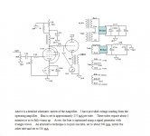
This is the schematic for the first amp that I built, using a straight isolation transformer with a filament transformer to boost the main B+ to 160V. OPTs were from Jack in Reno, as were the plate chokes. I sold that one on EBAY, to spur me to complete the second iteration which uses the transformer set from the guy in Hong Kong; I had received 2 sets nearly 3 years ago. Running 160V and 275 mA the amp is VERY linear and will do 15WPC.
As you can see it is a true ZERO NFB design, with NO TRANSISTORS. (use a transistor GO TO JAIL) Note the High S tube (7788) driving the CF output stage; the plate resistance is well under 1.5K on the drive tube for good frequency response.
The Hong Kong power transformer has 320V, 80V, and 160V secondaries, for bridge rectifiers, and 2 filament windings; 12.6VAC CT and 6.3V. Included in each set is a 5H 600 mA choke; I am adding a 30H 80 mA choke for the -320V grid supply. Plate chokes are still the Electra-print ones rated at 60H and 20 mA.
Since as pass tubes the 6S33S's were designed to run as CF's with fixed bias, this amp is extremely stable and well-behaved.
Attachments
- Status
- Not open for further replies.
- Home
- Amplifiers
- Tubes / Valves
- 6C33C-B. PP or SE ?