Dear Dannydanger,I am very pleased of your decision, needless to say.
Let me know please if you need further information on the circuitry and its performance.
In this topic I learned that some have built the Simplex but I wonder how many others have done that.
Anyone else ? What is your opinion on the sound ? Which OPT have you chosen ?
I would be grateful to know.
Ari
Good news, I heard back from Edcor yesterday and they can build a power transformer with the following specs;
700V C.T. (350 - 0 - 350) @ 50mA
600V C.T. (300 - 0 - 300) @ 300mA
6.3V C.T. (3.15 - 0 - 3.15) @ 7A
5V @ 7A
This will provide high enough voltages for tube rectification of both of the stacked B+ supplies, as well as enough filament current for the 6C33C, 6SN7, 5AR4 and 5C8S
I don't believe it should be a problem having both of the stacked, center tapped, supplies on the same transformer as long as they are rectified separately, anyone have thoughts on that? The top supply's C.T. would see the B+ of the other supply, will this matter?
They quoted me around $80 ea. for the transformers plus a $40 design fee. Not bad!
An externally hosted image should be here but it was not working when we last tested it.
Here's what I'm talking about, note the center taps highlighted in purple.
Last edited:
I think I just answered my own question, don't connect the center tap for the top supply as it's low side is the high side of the bottom supply. Thats not confusing at all. If someone would like to confirm, it would make me feel more comfortable.
Thanks Gabriel, I'll keep that in mind when I try the Borbely circuit. I'm still trying to figure out if I can build a stacked supply for the Simplex circuit using tube rectifiers per the sketch above. The bottom supply is a no brainer, but the question is how to handle the top supply, since its low side connects to the B+ of the bottom supply. It seems like I could omit the center tap on the top supply and it would reference the high side of the bottom supply. Both windings are going to be on the same transformer, so I'm assuming the center taps would reference the same ground, thus connecting the top supply's center tap to the bottom supplies B+ would short the top supply. Any thoughts on this would be appreciated. Hopefully my drawing makes it clearer what I'm trying to do.
Dear Dannydanger,
Just build the two power supplies separately and then :-
1) The lower power supply, meant for the driver, that I will indicate as B+1, must have
its negative grounded to the general ground.
The positive line is used normally as B+ for the driver's tubes.
2) The upper power supply has its negative line UNGROUNDED, but connected to the
B+1 of the driver's power supply. The positive of the power supply for the output
stage (B+2) goes to the 6C33s anodes through the OPT, as usual.
By doing so, you "stack" the two power supplies ( the power tubes' one B+2) on the top and the drivers tubes' one (B+1) on the bottom.
Have a look at the last two articles in the "Information" section of the site Polisois audio amplifiers and transformers : the presentation made at last year's European Triode Festival and the article whose title is "The beauty of low internal resistance valves". Thanks for not giving up. Once fully understood, and it might take some time, this novel circuit will look easy.
The reason for stacking the two power supplies is that the driver's anode has to be connected straight to the grid of the 6C33 and the B+1 positive of the driver stage to the cathode of the 6C33.
Thus, the anode load resistor of the driver (that has one of its terminals connected to the driver valve's anode and the other to the B+1 positive of its stage, which is also the negative of B+2, is directly connected to the grid and cathode of the output valve, in an unsurpassed direct connection way. Any, I repeat, any, slight change that occurs in the driver's anode load is perfectly and instantly "seen" by the 6C33 grid/cathode pair, from a tiny microsignal to a transient explosion.
There is no discrimination of any kind ( frequency, amplitude) and this explains why the listeners are surprised by the amplifier's performance.
Please do not hesitate to contact me.
Cheers,
Ari
Ari, I understand the function and design of the power supply. The issue is I only have room for one power transformer, so I would need the two B+ supplies on the same core and tube rectified, that's more the issue that I'm facing. I can rectify and filter them separately but I'm not sure how I can do that on the same transformer core and what will happen with the center tap for the upper supply?
Dannydanger;
I clicked on the icon of your post to see the image of your transformer but could not see it.
Could you post it again ?
Thanks
Arei
I clicked on the icon of your post to see the image of your transformer but could not see it.
Could you post it again ?
Thanks
Arei

Also, my output transformers arrived and I have a little more info on them. They are stated as being 150VA, I'm not sure what that equates to in power handling terms. 150VA/210VDC = 714mA max DC current?
Danny,
The power transformer and the schematic are OK and properly stacked in your drawing.
I don't see the filament windings. Kindly note that there is a big potential difference between them ( DC + AC ) and, if on the same bobbin, the insulation should be 2kV minimum, which is the current one ( and even 2,5 kV for a good quality power transformer).
Regarding the power handling capacity, I suppose it's 0K. Have you measured the DC resistance of the primary ( and possibly that of the secondary, but it's generally very low, less than 0,5 ohms ) ? Let me know please.
Ari
Hi TheGimp,
Sorry for being away sooo long, my Harley is a 1978 Superglide, forward controls,
16" spoke wheels 130 mm front and 160 mm rear tyre, ducktail, Electra Glide tank. It sports dragpipes with dB killers, but still sounds like a plane without an exhaust. The former owner painted it orange, frame, tank halves and fenders. I wil paint it flat black and the tank halves flat/gloss black (bottom top).
I have been busy with a lot of things, among others sourcing parts for my Duplex amplifier.
But it looks that I will be able to build pretty soon.
Dear Midlife,
I believe the best thing you could do is to get rid of your Harley, selling it at any price, invite your wife to stay with her mother for at least a couple of months and dedicate yourself full time to the Duplex. Keep your job to have enough money for the parts.
Ari
I believe the best thing you could do is to get rid of your Harley, selling it at any price, invite your wife to stay with her mother for at least a couple of months and dedicate yourself full time to the Duplex. Keep your job to have enough money for the parts.
Ari
Hi Ari,
I can imagine you feel that way, but I am fond of my wife and my Harley.
The Harley was acquired recently, this year, and today the 3rd of October my wife and I celebrated our 20th wedding anniversary.
We will visit a nice Greek restaurant this evening with our daughter to celebrate this.
You see, I just cannot spare the time to devote myself solely to Duplex, I wil promise you however, that I will put nice parts in it.
Sic Safco, Mallory, Jensen, Sangamo, Philips and Sprague capacitors, Allen Bradley resistors were it makes sense to use them and Beyschlag in other less critical places.
Although a lot of "iron" is used in this amplifier, I will try to fit it all in one housing and try to avoid humm, this should prove something of a challenge with 5 transformers and 1 choke. I fear for my back once the beast is finished and it should be moved from one place to the other.
Once I have all parts and aluminum for the chassis, I wil sit down with the parts, listen to music with a good whisky in my hand and once the parts know that they have to work together to be an amplifier, it will be alright and I will know where to put them.
I wish I thought of the above first, but credit for working like this and meditating together with the parts goes to Sakuma San.
No doubt you will understand that I look forward to building Duplex and listening to it with great anticipation.
OK Midlife, I hope you had an excelleny dinner and congratulations for your 20th anniversary. I wish you to celebrate together also your 50th anniversary.
You haven't followed my former advices and I can understand, but there is another one:
drink your whiskeys after you stop working on the Duplex.
All the best,
Ari
You haven't followed my former advices and I can understand, but there is another one:
drink your whiskeys after you stop working on the Duplex.
All the best,
Ari
PSU
Hi,
Is there a power supply for this amp I would like to try to build this amp, what are the spec for the OPT,and what is the R5 (400e 10BT?) value.
Thank you for the help
Hi,
Is there a power supply for this amp I would like to try to build this amp, what are the spec for the OPT,and what is the R5 (400e 10BT?) value.
Thank you for the help
And here is the simplest design with all the part values worked out for you:
http://www.mi.ru/~tube-art/6c33_amplifiers.htm
If you're starting from scratch I would try this one or the Borbely design.
An externally hosted image should be here but it was not working when we last tested it.
-- jose k.
Hi ovidiu1
The power transformer and also the OPT was made by a user from elforum.ro, his nickname is Lazaroiu.
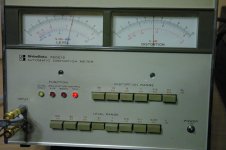
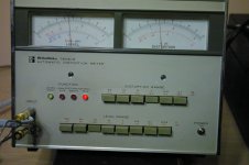
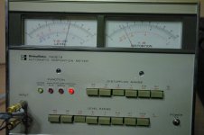
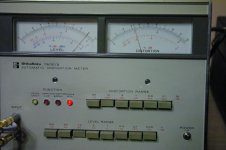
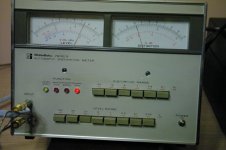
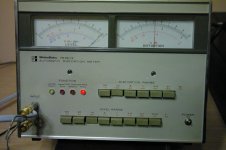
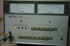
A few days ago i received from eBay a distortion meter.
I made some measurements,
Input 1kHz at 2.5v
4 ohm loading.
The last photo is the value without signal
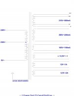
Because this amplifier will go to a friend of mine i will made another one but the power transformer will have more Ua values (180v 200v, 220v, 240v, 260v) and at least 900 mA.
After success with 6C33C I decided to do another project this time with GM70, I bought tubes, sockets and now I am looking for double C cores to make the OPT
The project will work at 950V or 1200V.
Ari if you have something to say about GM70 o will wait you to write on my GM70 thread. See you there.
Guys, I wish you good luck
.
The power transformer and also the OPT was made by a user from elforum.ro, his nickname is Lazaroiu.
A few days ago i received from eBay a distortion meter.
I made some measurements,
Input 1kHz at 2.5v
4 ohm loading.
The last photo is the value without signal
Because this amplifier will go to a friend of mine i will made another one but the power transformer will have more Ua values (180v 200v, 220v, 240v, 260v) and at least 900 mA.
After success with 6C33C I decided to do another project this time with GM70, I bought tubes, sockets and now I am looking for double C cores to make the OPT
The project will work at 950V or 1200V.
Ari if you have something to say about GM70 o will wait you to write on my GM70 thread. See you there.
Guys, I wish you good luck
.
Attachments
Hi Gabriel,
Your amplifier looks neat. Congratulations. Regarding the measurement I have some difficulties to understand the results. Could you please summarize with the following data:-
- Maximum power at 5% THD -
- THD at 12 W out put -
- Frequency range at 12W output.
- Also, are all the measurements made with a resistive 4-ohm load or 8-ohm load?
Regarding the GM-70 I am fond of this valve and have made some progress with a prototype, but had to give up for some time, due to other commitments.
Moreover, I am waiting for a special output transformer that is almost ready ( it is not one of my transformers ) that should simplify a lot the hi-voltage amplifiers layout still keeping the qsuality.
At present I am completing a Duplex that will be used at the European Triode Festival ( end November) for comparative tests between the Self compensated and the split core.
I hope to post a photo of the amplifier within end this week.
Ari
- Status
- Not open for further replies.
- Home
- Amplifiers
- Tubes / Valves
- 6C33C-B. PP or SE ?