Hi Ari
I will comment all the photos
Those measurements where made because I just receive the distortion meter.
The test frequency was 1 kHz at 2.5v. The distortion meter accepts 400Hz and 1 kHz. ..
All the measurements where made at 4 ohm load. I have only 4 ohm load resistor also my speakers are at 4 ohm.
First photo show us the THD at 2V=1W = 0.16%
Second show at 4.5V=5.06W=0.44%
Third show at 6.35V=10W=0.75%
Fourth show at 9V=20w=3.3%
Fifth show at 7.5V=14W=1%
Sixth show at 9.7v=23.52W=5.2%
The last photo show the output voltage without signal
These are my interpretation of this measurements
If something is wrong please correct me
The complete measurements will come soon.
I remember that the frequency range at 14W was 20Hz-23Kz without attenuation between those frequencies.
At -3db the frequency range was 12 Hz-45 kHz.
The frequency measurement were made at 14W and 8 ohm load
Best regards
Gabriel
Dear Gabriel,
Could you also measure the voltage between anode and cathode of the 6C33s ?
Also the DC current at idle.
If you do not have a test point for the latter measurement, take the DC resistance of the OPT first and then see what the drop of voltage acroos the OPT is.
Cheers,
Ari
Could you also measure the voltage between anode and cathode of the 6C33s ?
Also the DC current at idle.
If you do not have a test point for the latter measurement, take the DC resistance of the OPT first and then see what the drop of voltage acroos the OPT is.
Cheers,
Ari
Hi Ari
I run my 6C33C at 210V and 220mA, at higher current I have less distortion.
I will like to try to use the tube at higher anode dissipation at least 56 58W to see the difference but the power transformer was not made for such test
The OPT Ra is 550 ohm.
Son I will make complete measurements now the amplifier is in the working position I listen music on him. I have a small kind and I can not open it all the time. I will make test when I will be alone. But son I will take the amp at my office for complete measurements.
operating point
Hi all,
sooner or later I will start my 6C33 amp, I'm still wondering too about the best operating point for it.
I've run some simulation with Se amp cad (nice toy!) with 215V@220mA (but with a 500ohm transformer): the result is 13,7W with 9.3% of second harmonic distortion and 0.2% of third (at full power)
I'm not in a position to be able to say if this is a good figure or not, so I'm asking your opinions. This operating point seems quite popular.
I will use a 600 ohm transformer, this leads to 12.3W with 8.3% IIh and 0.4% of IIIh. Sure these are not the limits of the valve, right?
Just to experiment (before heating up the soldering iron), I'v erun a simulation for a parallel SE: the limit (not considering that the valve should be used with <250W if run near the maximum dissipation) seems to be almost 50W (with the same 600ohm transformer) at 370V@160mA each, but this time with 12.8% of IIh and 0.5% of IIIh. The question is: can it work? How is it going to sound?
But most of all, the figures of distortion are at full power: what if I usually run the amp far from full power output? Is the sound going to follow the percentage of the distortion or which other parameter should be kept under control in order to define the "best sounding" operating point?
Yeah, I know: too many questions, and most of them also a little bit naive😱
Ciao
Paolo
Hi Ari
I run my 6C33C at 210V and 220mA, at higher current I have less distortion.
I will like to try to use the tube at higher anode dissipation at least 56 58W to see the difference but the power transformer was not made for such test
The OPT Ra is 550 ohm.
Son I will make complete measurements now the amplifier is in the working position I listen music on him. I have a small kind and I can not open it all the time. I will make test when I will be alone. But son I will take the amp at my office for complete measurements.
Hi.
I am referring first to Gabriel's messages.
I know the 6C33 better than any other tube and have used it in many circumstances.
The anode/cathode voltage you stated is OK, maybe the best, and the idle current too.
To summarize : optimum use = 200-220V a/k and 200-220mA idle. Easy to remember.
This corresponds to a plate dissipation ( average ) of 44 W well below the max.of 60W.
With the single ended topology it is very hard to exceed, with single ended topology and triodes, an output power of 25% with respect to the plate dissipation, unless you add too much distortion.
Therefore 25% of 44 W means 11W only.
This does not match with the figures you stated in your former message ( 23,52 W at 5,2% ) as it would be an outstanding result never reached before.
The only explanation I can think about is that your distortion analizer could be wrong, either in voltage and/or distortion figures.
Also, it could give "peak" measurements and not RMS.
From the "Simplex" I get 12W ar 5% which I consider an excellent result ( in line with the software mentioned by Pidigi). At 15W I get 6,5 % distortion. The impedance of the OPT is 600 ohms and the DC resistance of the primary 40 ohms.
At 220mA the voltage drop across the primary is 8.8V meaning anout 2W of DC power dissipated, which is acceptable.
Please continue your checks and let us know. I have quoted above what I consider to be the best operational figures.
Regarding Pidigi's statement, I found ( measured ) that a comfortable listening level corresponds to 6W of output power, in an average sized room ( 6m x 4,5 x 3m h )
with nominal 90 dB sensitivity enclosures.
When more power is required the "Duplex" almost doubles the output power, with its pair of 6C33 per channel, paralleled and there, you cannot use it at full power in my room.
Regarding the frequency range it depends on the type of output transformers ( see with Googlre > European Triode Festival 2008 > ETF2008 > Lectures ) or my AES papers and presentations Barcelona 2005 - Amsterdam 2006 - Paris 2007 .
For the self compensated type = 35 Hz - 45 kHz are the rule and for the SC-SCC from less than 10Hz to 40-45 kHz.
The OPT for ther Duplrc has an impedance of about 400 ohms. Voltage and idle current per tube remain the same. Orientatively, the negative bias varies from 75V to 85V, depending on the condition and charcteristics of the tubes.
Cheers,
Ari
Hi Ari
Believe me all the measurement are not fake is not in my nature to show what is unreal.
I was surprise also because Borbely in his report has some measurements at 8 ohm loading.
Soon I will make all the measurements all together at 8ohm loading.
The 9.7v measured by the distortion meter was measure also with my digital multimeter with measure V rms until 2kHz.
I will post photos whit all the equipment on the table when I will made the last tests.
The distortion meter was test firs whit my cd player using a Sony test CD special made for repairing CD players.
Best regards
the link to the Borbely amplifier
www.borbelyaudio.com/adobe/15wse.pdf
Last edited:
considerations
Hi Ari,
thanks for the reply.
A friend of mine is asking about a powerful amplfier: he owns 84dB (in my opinion even less) lodspeakers. So a minimum acceptable will be 30W of true amplification, no lies here🙂
Moreover I have build electrostatic loudspeakers, the first experiments (ouch, 15 year ago ) was a very good sounding louspeaker, but very inefficient: I managed to clip a 150W mosfet amplfier during a sax track reproduced at realistic level 😉.
My question was actually focussed on the different sound that an operating point with higher anode voltage and lower anode current is going to give, compared to the proposed "standard" operating point, and if it possible to correlate the final result, in terms of quality, with the percentage of second and third harmonic distortion.
Thank you in advance,
Paolo
Hi Ari,
thanks for the reply.
A friend of mine is asking about a powerful amplfier: he owns 84dB (in my opinion even less) lodspeakers. So a minimum acceptable will be 30W of true amplification, no lies here🙂
Moreover I have build electrostatic loudspeakers, the first experiments (ouch, 15 year ago
) was a very good sounding louspeaker, but very inefficient: I managed to clip a 150W mosfet amplfier during a sax track reproduced at realistic level 😉.My question was actually focussed on the different sound that an operating point with higher anode voltage and lower anode current is going to give, compared to the proposed "standard" operating point, and if it possible to correlate the final result, in terms of quality, with the percentage of second and third harmonic distortion.
Thank you in advance,
Paolo
.....
Regarding Pidigi's statement, I found ( measured ) that a comfortable listening level corresponds to 6W of output power, in an average sized room ( 6m x 4,5 x 3m h )
with nominal 90 dB sensitivity enclosures.
When more power is required the "Duplex" almost doubles the output power, with its pair of 6C33 per channel, paralleled and there, you cannot use it at full power in my room.
Regarding the frequency range it depends on the type of output transformers ( see with Googlre > European Triode Festival 2008 > ETF2008 > Lectures ) or my AES papers and presentations Barcelona 2005 - Amsterdam 2006 - Paris 2007 .
For the self compensated type = 35 Hz - 45 kHz are the rule and for the SC-SCC from less than 10Hz to 40-45 kHz.
The OPT for ther Duplrc has an impedance of about 400 ohms. Voltage and idle current per tube remain the same. Orientatively, the negative bias varies from 75V to 85V, depending on the condition and charcteristics of the tubes.
Cheers,
Ari
Dear Paolo ( pidigi ) .
Regarding a more powerful amplifier ( single ended ) I can recommend the King III
( three parallel 6C33 per channel that deliver 50W effective), and use the self-compensated OPTs that can handle 1A of DC idle current.
The frequency range goes from 25 Hz to 35kHz at -3dB ; 2.5% distortion at 30W and 6.2% distortion at 50W.
The OPT uses C-cores and the DC resistance of the primary is below 10 ohms.
This amplifier has been described in the July 2004 issue of AudioXpress and ( in Italian language) in N°62-64 of COSTRUIRE HI FI .
The OPTs weight about 12kg each - and, for destinations to the States, are shipped unassembled. The assembly requires about 30 minutes.
In Italy there are at least 5 King III amps in operation. For reference you can apply to
Mr. Mauro Cauli ( mauro_cauli@virgilio.it ), who has built a couple of King III.
Diy guys attending this forum that need to read the article on AudioXpress, are kindly asked to confirm their interest and I'll post the pdf file.
The second part of your message concerns a higher anode/cathode voltage for the 6C33. As you know, the idle operating point would move to the right, in the diagram, where the grid curves are crowded and, in order not to exceed the recommended 60W of dissipation, the anode current should be lowered. This means a higher distortion.
If you choosed, for instance, an a/k voltage of 300V, you should not exceed 200mA of idle current. Moreover, you would require a higher bias for the 6C33 and, consequently, the driver would be forced to supply a wider swing, to reach full power.
The result is additional distortion and faster aging of the valves.
With this in mind, I would choose a lower plate dissipation, a higher anode current and a lower driving swing. If you need ONLY 30W, you can even use a lower plate voltage ' say 200V and an idle current of 250mA ( Pa = 50W ) and the ovverall result would improve.
Cheers,
Ari
Last edited:
Hi Paulo
Many people who need more power for their speakers use a bi amping system, for the bass a PP amplifier and for midrange and high a SE amp.
Best regards
Many people who need more power for their speakers use a bi amping system, for the bass a PP amplifier and for midrange and high a SE amp.
Best regards

I have built a number of SE amps over the years; have often worked with Jack at Electra-Print to build custom OPTs for my amplifiers. On his site he shows a direct coupled plate choke driven amp. I really pushed the envelope on my design; running my 6S33S's as CATHODE FOLLOWERS, which as series regulators is AS INTENDED. Using the plate loaded drive provides the necessary driver voltage swing. Needless to say it blows the doors off of 300B amps; more power, much better damping, better linearity and excellent overload recovery. Of course the drivers are high S tubes and it is a zero FB design.
wow, this seems very interesting! Any schematic available?
Ciao
Paolo
Ciao
Paolo
I have built a number of SE amps over the years; have often worked with Jack at Electra-Print to build custom OPTs for my amplifiers. On his site he shows a direct coupled plate choke driven amp. I really pushed the envelope on my design; running my 6S33S's as CATHODE FOLLOWERS, which as series regulators is AS INTENDED. Using the plate loaded drive provides the necessary driver voltage swing. Needless to say it blows the doors off of 300B amps; more power, much better damping, better linearity and excellent overload recovery. Of course the drivers are high S tubes and it is a zero FB design.

great, thank you!
I did an article on this for the late great Charlie Kittleson's VTV mag. So I have schematics and pix and even SPICE simulations. They are on another computer so I will dig the article up and post it.
I did an article on this for the late great Charlie Kittleson's VTV mag. So I have schematics and pix and even SPICE simulations. They are on another computer so I will dig the article up and post it.
By any chance would you have a reprint of that article? I am very interested. Thanks!
Lo-tse
Yup I want to build the one with the octal front end. Mine runs at 170V and 275 mA; fixed bias Cathode Follower. Bias is about -43V.
I got a set of those Hong Kong OPT/power sets a couple years ago; now I have no excuse procrastinating the build.
(right after I get the GU50 amp done...
I got a set of those Hong Kong OPT/power sets a couple years ago; now I have no excuse procrastinating the build.
(right after I get the GU50 amp done...
I just edited the article with a detailed schematic that I 'reverse engineered' from the built amp on the auction site. However I can't figure out how to post it; it is a Power Point sketch, and the article is in Word.
Hi,
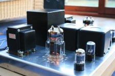
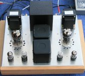
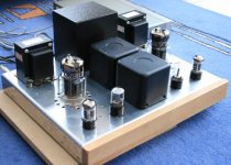
I am back with my SE 6c33c amp project, based on Borbely’s audio schematics.
In fact, I have just finished it some days ago and since then, I have made some tests.
I stopped the project in July 2010 because I had a stupid problem with the mains transformer that got burned. Unlucky a piece of leg of a resistor that I had cut off during the construction, kept hided inside, and when I moved the amp to connect to the rest of devices, the piece of leg made a short-circuit in the mains transformer and it burned up. I got so angry that I decided to stop it for a while.
I re-started last December with a new transformer and finished it.
This amp is extraordinary! Transparent, precise, with a perfect balance between the 2 channels. The sound image is perfect, just in front and in the middle of the 2 speakers. One can distinguish perfectly the different instruments of a big orchestra and the voices, men or women, are much more clear than with the other amps I have known. It is not much powerful, but it is enough for my speakers (92.5 dB) since I am able to run it without overpassing the middle of the maximum volume.
I am still on testing, and the only issue is that I don’t have a distorsion analyser. And I feel that there is a little bit of distorsion at high volume. I am wondering if I will manage to fine-tune it by ear, by changing slowly and progressively the resistance of P1.
I think that the distorsion impacts the high frequency sounds, which seem to me less powerful compared with other amps used for testing. Contrarily, the low frequency sounds are very strong and I do not like this. If any one of you can give me ideas on possible reasons for this, I would be very grateful.
Any way, I still consider that it is an excellent amp and I will find the solution to correct this “subjective” problem of lack on high frequencies.
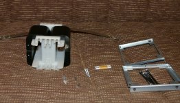
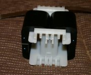
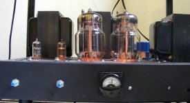
Here you have 2 pictures (still remains to put it on a platform with spikes):
José
I am back with my SE 6c33c amp project, based on Borbely’s audio schematics.
In fact, I have just finished it some days ago and since then, I have made some tests.
I stopped the project in July 2010 because I had a stupid problem with the mains transformer that got burned. Unlucky a piece of leg of a resistor that I had cut off during the construction, kept hided inside, and when I moved the amp to connect to the rest of devices, the piece of leg made a short-circuit in the mains transformer and it burned up. I got so angry that I decided to stop it for a while.
I re-started last December with a new transformer and finished it.
This amp is extraordinary! Transparent, precise, with a perfect balance between the 2 channels. The sound image is perfect, just in front and in the middle of the 2 speakers. One can distinguish perfectly the different instruments of a big orchestra and the voices, men or women, are much more clear than with the other amps I have known. It is not much powerful, but it is enough for my speakers (92.5 dB) since I am able to run it without overpassing the middle of the maximum volume.
I am still on testing, and the only issue is that I don’t have a distorsion analyser. And I feel that there is a little bit of distorsion at high volume. I am wondering if I will manage to fine-tune it by ear, by changing slowly and progressively the resistance of P1.
I think that the distorsion impacts the high frequency sounds, which seem to me less powerful compared with other amps used for testing. Contrarily, the low frequency sounds are very strong and I do not like this. If any one of you can give me ideas on possible reasons for this, I would be very grateful.
Any way, I still consider that it is an excellent amp and I will find the solution to correct this “subjective” problem of lack on high frequencies.
Here you have 2 pictures (still remains to put it on a platform with spikes):
José
Attachments
- Status
- Not open for further replies.
- Home
- Amplifiers
- Tubes / Valves
- 6C33C-B. PP or SE ?