OllBoll, I never said that I did build it
looking from few years perspective, head full with other things, it seems that it could work and , maybe even without special attention and tuning of caps, it must work from cold as intended
why don't you try it - if you put nice fuse in rail, there is no danger for anything
well, I certainly even forgot that I ever put a minute in that schematic .... and obviously I did

why don't you try it - if you put nice fuse in rail, there is no danger for anything
Yup it might be worth a try. And while I'm at it I think I'll add another circuit I might try next weekend:
I always liked the sound of my only degenerated inductor loaded zen amps but their distortion performance is not good enough to push the circuit into the 20-40W range.
It would be very cool to try a current feedback beast mosfet variant. My speakers can be wired as 16 ohm instead of 4 which should give 30-40W with 48V rails @ 2A.
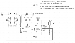
But while I could place the CCS on top which I'm sure would work fine I believe there would be a few advantages putting it on the bottom. That is if I've understood correctly and the following is true:
- With the 1R on the bottom working as 1R source degeneration for the bias, it should be very stable with no risk of thermal runaway.
- The mosfet is still in common-source mode => lots of gain
- There is no significant added distortion due to all the floating going on.
- In theory shouldn't it also have less of an on/off thump since the output cap is loaded with a lower voltage thus contains less energy?
Addition: the small resistors + cap close to the 1R current feedback are for low frequency stability, without them it starts to oscillate like crazy. Values are what I think I used in the latest experiment with the normal Mu CCS variant, should work here too.
Attachments
Last edited:
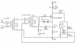
And of course I made a mistake in the schematic =)
The current feedback should be taken from the other side of the smaller output capacitor: from the middle of the voltage feedback network.
The current feedback should be taken from the other side of the smaller output capacitor: from the middle of the voltage feedback network.
not so sure that you're getting there in common source territory - for that you need to have Ugs generator floating (with gate), while you have it nailed to GND , as I understood drawing
OK, when done like you did it, it have influence on thermal runaway (voltage sag across inductor increasing Ugs) but no common source operation
so, pick your poison, sometimes you can't get small shot in beer mug, just one of them
OK, when done like you did it, it have influence on thermal runaway (voltage sag across inductor increasing Ugs) but no common source operation
so, pick your poison, sometimes you can't get small shot in beer mug, just one of them
not so sure that you're getting there in common source territory - for that you need to have Ugs generator floating (with gate), while you have it nailed to GND , as I understood drawing
OK, when done like you did it, it have influence on thermal runaway (voltage sag across inductor increasing Ugs) but no common source operation
so, pick your poison, sometimes you can't get small shot in beer mug, just one of them
Unless you add even more transformers =)
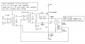
The question is if my source impedance is low enough to run it in the maximum voltage gain config: It is 100 ohm, too high with hockey puck? Maybe I need to add the JFET buffer from the F6 in the front.
One option would be to wire the input mosfet in 2:1+1 step-down. Add a JFET buffer and add a small preamp before the buffer.
Attachments
well, that's whole another issue - source Rout
what I'm saying - if you want anti-thermal runaway , that's one thing
if you want common source, that's another thing
these two demanding different biasing circuit reference
what I'm saying - if you want anti-thermal runaway , that's one thing
if you want common source, that's another thing
these two demanding different biasing circuit reference
well, that's whole another issue - source Rout
what I'm saying - if you want anti-thermal runaway , that's one thing
if you want common source, that's another thing
these two demanding different biasing circuit reference
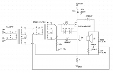
This might be a dumb question, but isn't the DC bias circuit independent of common drain vs common source? Such that I could basically replace the 193V with an 1R source resistor like in the first circuit here and the bias circuit could stay the same since with respect to DC it is the same.
In the end I would want:
1. Stable bias with no or minimal thermal runaway since I wouldn't have an active CCS to cap the bias current.
2. Maximum mosfet open loop gain to use for current feedback => as little degeneration as needed to satisfy 2.
3. Reasonable on-off thump. If too big I'd have to reduce the output cap capcaitance.
A more standard circuit would be the second circuit which is a normal common-source with CCS on top. The transformer capacitor could still connect to above the source resistor which if I've understood correctly will amplify as with no degeneration, but with slightly higher distortion.
In the end I might build both floating common drain and normal common source and see how they perform. It's in the cases when I build it and realize it really doesn't work at all I learn the most =)
Attachments
just take a good look at F6, and biasing references lower vs. upper half
analyzing upper half, of interest here , you have common source arrangement, but no influence on thermals via resistance in source
I'm sorta shorter brain-wise these days (than usual) so it's possible that I'm brainfarting here 🙂
edit: ignore me - you're good ; both bias network and source includes are referenced to same point - GND
told ya, I'm not one to thrust, these days 🙂
Last edited:
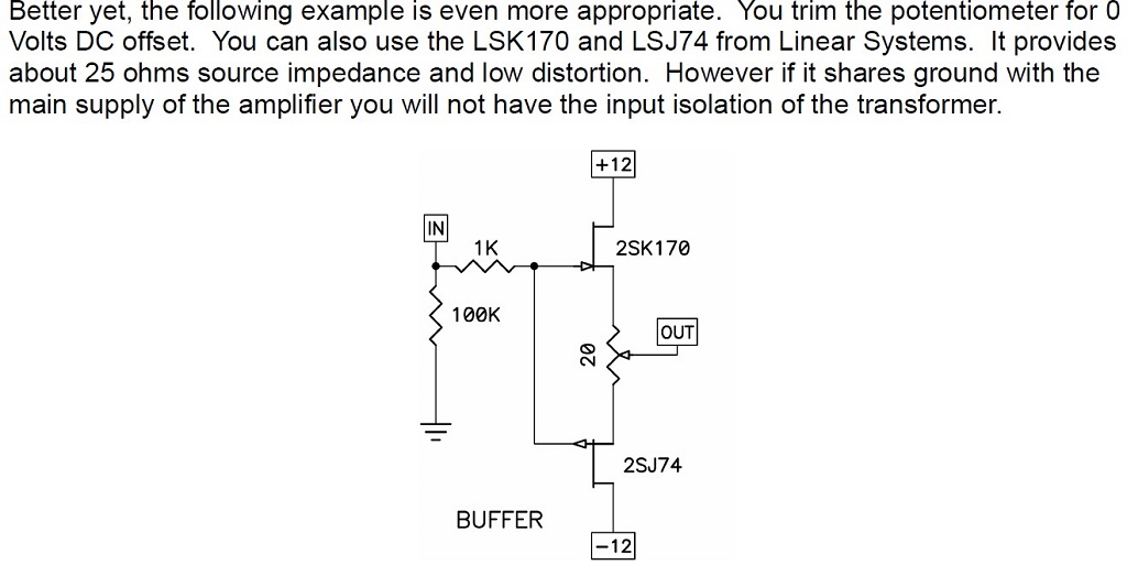
I'd like to put a simple buffer on my input transformer but I'm puzzled by the following statement. If my +/-12 VDC supply for the input buffer shares the same ground as my 60VDC main supply I lose the isolation of the transformer?
I'm use to typing all supplies into a single star ground.
Regards,
Dan
I'm use to typing all supplies into a single star ground.
Regards,
Dan
Attachments
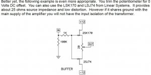
I'd like to put a simple buffer on my input transformer but I'm puzzled by the following statement. If my +/-12 VDC supply for the input buffer shares the same ground as my 60VDC main supply I lose the isolation of the transformer?
I'm use to typing all supplies into a single star ground.
Regards,
Dan
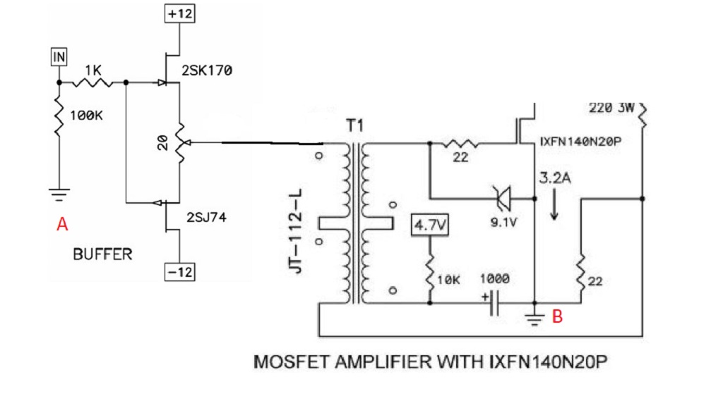
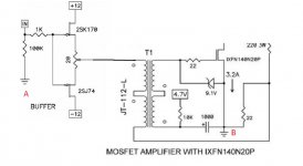
Even without a buffer the amp does not have the isolation. To have true isolation you can't connect the primary and secondary but the smart part of this circuit is the feedback loop from the output to the negative primary. This loop esentially removes the isolation.
As long as your grounding scheme is sound, that shouldn't be a problem, however.
This is a separate issue, but to simplify things why don't you regulate down to the voltage you want from the main supply, rather than do separate transformers.
you have all isolation needed here - role of xformer (signal one, feeding SIT gate) is to have primary at gnd potential, and secondary at SIT biasing voltage potential
go figure 🙂
go figure 🙂
I'm assuming Pa's suggestion is to not tie the buffer's PS ground to the main PS ground? As far as regulating the main power supply down that is beyond the scope of my skills because the main PS is unipolar and the buffer requires a bipolar supply.
Regards,
Dan
Regards,
Dan
Attachments
We can make it work.
I need to sleep but Zen Mod might show how to do it with a circuit diagram.
I need to sleep but Zen Mod might show how to do it with a circuit diagram.
Hi Dan,
I'm building the same buffer, and had the same question. To solve it, the easiest (quickest) would be to make the buffer it's own stand-alone unit, thats what I'm doing. Right now it's being fed direct from an iphone, sounds excellent, but needs a bit more gain than the phone offers.
I'm building the same buffer, and had the same question. To solve it, the easiest (quickest) would be to make the buffer it's own stand-alone unit, thats what I'm doing. Right now it's being fed direct from an iphone, sounds excellent, but needs a bit more gain than the phone offers.
Attachments
Ha! You have approximately the same heat sinks as me! I’m trying to build a monster single chassis solution that will take a small crane to lift into place. The reason I want to include the buffer internally into my design is so I won’t have any ‘compatibility’ issues with any preamp I choose.
Regards,
Dan 🙂
Regards,
Dan 🙂
I'm assuming Pa's suggestion is to not tie the buffer's PS ground to the main PS ground? As far as regulating the main power supply down that is beyond the scope of my skills because the main PS is unipolar and the buffer requires a bipolar supply.
Regards,
Dan
Hi Dan,
I'm building the same buffer, and had the same question. To solve it, the easiest (quickest) would be to make the buffer it's own stand-alone unit, thats what I'm doing. Right now it's being fed direct from an iphone, sounds excellent, but needs a bit more gain than the phone offers.
The two grounds need to be connected to complete the circuit. Even with the buffer as a stand-alone unit the two grounds still connect through the negative side of the interconnects.
Whether or not a transformer provides isolation depends on the way it is connected. If the primary and secondary are not connected then there is transformer isolation. Perhaps that is the context of quote in post #1170. Also stated by OllBoll in post #1171. However, the transformer primary and secondary are connected in the BAF2015 Amp circuit.
Not connecting the two grounds only work if the transformer primary and secondary are not connected.
I'm confused now ....... what is a scope of questions - solving supply for buffer, or someting with GND?
GND is established in said amp, by someone smarter than we Greedy Boyz are, so please bugger off of GND
regarding buffer PSU - it's simple - choose your poison - making small bipolar PSU for said buffer, or insert it in monopolar amp PSU, but then you need small cap on buffer input and bigger cap on buffer output
go see Singing Bush, Schade iteration, to see one way
- Home
- Amplifiers
- Pass Labs
- 50w Single-Ended BAF2015 Schade Enabled