No pre-amp or anything is connected to the amp. I connected 10k at the input did not work. I shorted the input to ground did not work. I will try the resistor across the fets next. Thanks
Try with connected preamplifier first maybe no need for input resistor ?
If anyways amplifier need rca input resistor then choice can be values start first from low 500R and go high to 5K.
Find what work good
Best regards 🙂
If anyways amplifier need rca input resistor then choice can be values start first from low 500R and go high to 5K.
Find what work good
Best regards 🙂
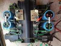
Thank you Soundhappy and Vdi_nenna for your advices. I finally fixed the problem. I reversed the secnondary connection of the input transformer, now no more oscilations.
But I am facing another issue and need your expert advice again, please.
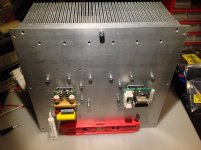
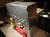
Heat: my heatsink measures 4.5-inch in diameter, 1-inch tall fins and 13-inch long. I am running a fan at full speed blowing the air thru the entire heatsink like a tunnel. I do not have specs for the heatsink but from the size and mess, it should be enough keeping the mosfet comfortable expecially with force-air cooling.
The CCS mosfet runs very hot. after 5 minutes of running(input grounded, 6 ohm dummy load), the heatsink becomes quite hot and cannot keep a finger on it for more than a few seconds. I worry the amp will be damage if I run it longer. The audio mosfet runs much much cooler. Is this normal? could there be still some oscillation that cause running hot? how
should i troubleshoot it?
How do I upload a picure of my amp to show you what I am making?
But I am facing another issue and need your expert advice again, please.
Heat: my heatsink measures 4.5-inch in diameter, 1-inch tall fins and 13-inch long. I am running a fan at full speed blowing the air thru the entire heatsink like a tunnel. I do not have specs for the heatsink but from the size and mess, it should be enough keeping the mosfet comfortable expecially with force-air cooling.
The CCS mosfet runs very hot. after 5 minutes of running(input grounded, 6 ohm dummy load), the heatsink becomes quite hot and cannot keep a finger on it for more than a few seconds. I worry the amp will be damage if I run it longer. The audio mosfet runs much much cooler. Is this normal? could there be still some oscillation that cause running hot? how
should i troubleshoot it?
How do I upload a picure of my amp to show you what I am making?
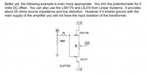
you need to adjust "4V7"** voltage to get approx. half (or few volts down) rail voltage at drain of lower mosfet
that way mosfets will be equally hot
heatsink size , even with fan - if too hot , more Aluminum
**ref. to pic in post #1
that way mosfets will be equally hot
heatsink size , even with fan - if too hot , more Aluminum
**ref. to pic in post #1
I adjusted the bias now the mid point--output before cap is around 29v. both mosfets are running closer in temperature. Thanks.

put foam or even better - sponge insert on output side of heatsink tunnel, to plug that open space , and route air stream strictly through fins area


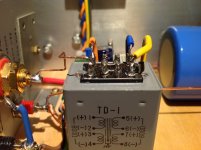
Here is my amp ready for a spin. However, it runs very hot. I may have to rebuild it with bigger heatsink
My mono block's heat sinks are huge and heavy ones , 3.2A current make them hot but no need for air ventilation.
Attachments


....I reversed the secondary connection of the input transformer, now no more oscilations....
@ Dmy
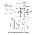
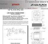
What is the input transformer brand, model You use ? Jensen, Cinemag or..?
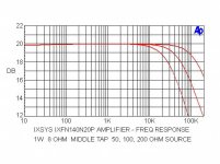
Just for remembering: optimal wideband frequency response is easy to get with the Jfet's impedance buffer connected
to the hockey puck's amplifier game 🙂 Greetings

Attachments
Attachments
Question about the schematic in post 12.
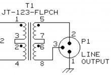
The Jensen transformer's physical polarity, is it flipped manually to match the schematic or does the polarity markers end up being marked the same as the schematic?
I know it's stupid question, but I'm afraid to wire it incorrectly.
I guess I can place the secondary in series and just flip the connection to the circuit board or next connection points. 😱
Sorry, I have a little mental block with this for some reason. 😱
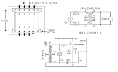
Imho is the pins numbers and the dot's symbols important to connect them the same order
like was show on the official Papa schematic :
secondairy center connection is pin 5 connected with pin 8.
Then pin 6 to 10 K resistor and pin 7 to 22 Ohm resistor.
Tamura have not the dots symbols but is equivalent of (+) polarity output pin 🙂
like was show on the official Papa schematic :
secondairy center connection is pin 5 connected with pin 8.
Then pin 6 to 10 K resistor and pin 7 to 22 Ohm resistor.
Tamura have not the dots symbols but is equivalent of (+) polarity output pin 🙂
Attachments
Last edited:
- Home
- Amplifiers
- Pass Labs
- 50w Single-Ended BAF2015 Schade Enabled