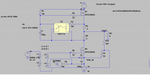
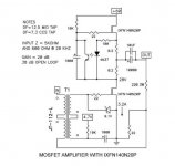
Is the polarity set right on the input transformer secondary? Looks different from original schematic.
Input is correct - the original schematic has the orientation of the windings 'reversed' as opposed to 'mirrored'. The part in eagle goes into the schematic as it is, so it looks different.
Any thoughts or input? Not shown in the top layer which is GND. I had to pop a few 0r bridges in to separate the high current ground from the rest, so that may explain a thing or two.
Any comments? I'm super happy to keep at it for the benefit of all if there's interest? Equally, I can remove the reg - I popped it in with the idea that I could modulate the cascode ala Ven v3, but I'm not sure that's required anymore, so removing that part frees up a bit of real estate and voltage.
Last edited:
...Actually. Any reason we cant make this a bipolar supply version? Get rid of the output caps? It seems relatively straigtfoward. :dunce:
So thinking aloud...
Reg the +ve and -Ve rails, and make that adjustable, hence you could tweak the rails until the output sits right at 0V.
Have I completely lost the plot here?
Reg the +ve and -Ve rails, and make that adjustable, hence you could tweak the rails until the output sits right at 0V.
Have I completely lost the plot here?
...Actually. Any reason we cant make this a bipolar supply version? Get rid of the output caps? It seems relatively straigtfoward. :dunce:
I suggested this way back in post 133. Subsequent SPICE modeling suggested it might have high DC offset at power on/off causing turn on/off thumps, so I got scared off. You can always try it and see.
Well I should have looked at the circuit better before I posted it. The 22 ohm resistor at the output should be at ground not on the supply.
Cool, I'll make the change and model up a power supply circuit and see how the turn on behavior looks 🙂
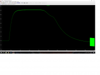
quite the thump!
...can be seen in the attached!
I cheated and subbed in 2 x irfp240's in lieu of the hockey pucks as that was a bit quicker for me to do.
Guess I'll try a pass fet on the rails for a slower turn on...
...can be seen in the attached!
I cheated and subbed in 2 x irfp240's in lieu of the hockey pucks as that was a bit quicker for me to do.
Guess I'll try a pass fet on the rails for a slower turn on...
Attachments

...and thats not very helpful either. I suppose it's a moot point as due to operating point variability as it warms up as well.
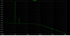
It was also interesting to see how much PSU noise got through to the output once I built the powersupply model on... 30 - 40mV or so of ripple on the output.
So what I'm taking away from this is that cap output and a single supply are good ideas (who would have thought nelson would have know that to start with! 🙂 ) for this circuit. I also read that the srpp type stages are known for not having good psrr, so the pass fet in my previous pcb design is a good idea.


Hi RobLK,
That looks pretty good I gotta say. I personally don't intend to use one of the hockey puck Fets (I've some irfp150's here for a lower powered version).
I'm very happy to do the design work on a PCB for them though - does anyone have the eagle part for a hockey puck?
That looks pretty good I gotta say. I personally don't intend to use one of the hockey puck Fets (I've some irfp150's here for a lower powered version).
I'm very happy to do the design work on a PCB for them though - does anyone have the eagle part for a hockey puck?
Well, no reason not to go ahead with a design any way. It won't be too hard to drop the puck part in after.
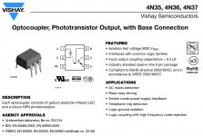
No connection to pin 6 on 4N37 opto-coupler? Just pins 1, 2, 4 and 5?
What about pins 6 base connection ?
Attachments

- Home
- Amplifiers
- Pass Labs
- 50w Single-Ended BAF2015 Schade Enabled