aha
I believe 10K resistor ditto across input RCA connector will suffice , or even better , on amp pcb , between In and GND
however , Pa still need to confirm critical value of that resistor
I believe 10K resistor ditto across input RCA connector will suffice , or even better , on amp pcb , between In and GND
however , Pa still need to confirm critical value of that resistor
Yeah, he said start with 10k, work your way down gradually until motor boating stops. The idea being you need value as high as possible but not too high as to allow oscillating.
Are the .2 ohm resistors 3w power resistors? I'm only assuming because of the resistance value.
thanks,
Vince
thanks,
Vince
Are the .2 ohm resistors 3w power resistors? I'm only assuming because of the resistance value.
thanks,
Vince
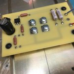
@ Vince
Mr Rothacher CCS circuit photo show power ones.
Best regards 🙂
Attachments
I'm going to go with a 24v 500va (10.4A) Antek toroid per channel. Looking to get 32-33v and 1.6 to 2 amp from circuit. They are out of the 24v 600va (one left).
What do you guys think?
Have the DIY Audio PS board and eight 33kuF caps coming in! 😉
BTW- With the above power supply, I calculate 15-16w output based on 25% efficiency of the SE output. Sound about right?
Vince
What do you guys think?
Have the DIY Audio PS board and eight 33kuF caps coming in! 😉
BTW- With the above power supply, I calculate 15-16w output based on 25% efficiency of the SE output. Sound about right?
Vince
All that sounds good to me - although I'm not sure about your PSU voltage there. I seem to recall ZM saying an end voltage of 1.2 x ac voltage is a good guide for a PSU voltage for a class A amp. So that's about 30 - 31V...
I've a build part way done, using about 40K uF per channel. I figure that'll be sufficient!
I'm still faffing about on a pcb for it though. What are you planning on using?
I've a build part way done, using about 40K uF per channel. I figure that'll be sufficient!
I'm still faffing about on a pcb for it though. What are you planning on using?
I was trying to learn a PCB design program for direct deployment to fab house.
Learning curve is a pain.
Learning curve is a pain.
I was trying to learn a PCB design program for direct deployment to fab house.
Learning curve is a pain.
Indeed it is, though the curve flattens out with more time. I spent some time with Kicad last week and found the first hour or so to be very slow, but the program seemed much more friendly by the end.
Ive most of a PCB design done - I'll drop it here when I get home. I tend to struggle a bit with analysis paralysis so I'd appreciate feedback and suggestions.
......I've a build part way done, using about 40K uF per channel. I figure that'll be sufficient!
I'm still faffing about on a pcb for it though. What are you planning on using?
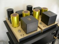
Last days i was lucky to afford 2 caps like big can's 100 000 uF , rated max 80 V.
After add them with other smaller ones for total capacity around 200 000 uF each channel.
They are in customs now hope get them at my home next week.
Better bass and fortissimo garantie with single-ended amp

On the photos Hiraga's with one power transistor...my suggestion but with lot of heat sinks
Attachments
Awesome. I've a set of 8 100000uf 30V caps here that I intended for a Pass amp at some juncture. Theyre just a bit too huge to fit in anything!
Awesome. I've a set of 8 100000uf 30V caps here that I intended for a Pass amp at some juncture.
Theyre just a bit too huge to fit in anything!
Smaller caps first + one 100 000 uF for each channel is always too huge for your chassais ?
Attachments
I'll post a picture later on. They're big. I reckon it'd look like a small motor block if I used the lot.
That said I've no idea what the physical size of a 80V 100000uF cap is! That'd be a whopper I imagine...
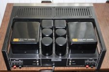
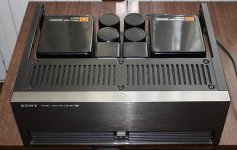
Sony Vfet Amp is it? Nice.
That said I've no idea what the physical size of a 80V 100000uF cap is! That'd be a whopper I imagine...
Sony Vfet Amp is it? Nice.
I'll post a picture later on. They're big. I reckon it'd look like a small motor block if I used the lot.
That said I've no idea what the physical size of a 80V 100000uF cap is! That'd be a whopper I imagine...
Sony Vfet Amp is it? Nice.
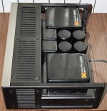
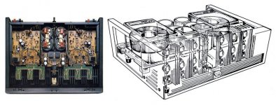
Yes is Vfet amp from Sony TA-N7.
High build quality we can transpose to Schade 50W

Attachments
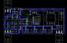
PCB
PCB, where I kinda stopped - basically a one sided design - I reckon I can improve it quite a bit by two siding it.
Comments welcome!
I did go to the point of matching it (i think) to the ums spec at some point, just for learning. Not sure if this board is that, but it's easy enough to do.
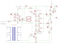
Note, I also included a circuit for the bias, and for a reg to feed the amp itself.
edit - the resistors r24 -28 are intended as jumpers to set the mu level
PCB, where I kinda stopped - basically a one sided design - I reckon I can improve it quite a bit by two siding it.
Comments welcome!
I did go to the point of matching it (i think) to the ums spec at some point, just for learning. Not sure if this board is that, but it's easy enough to do.
Note, I also included a circuit for the bias, and for a reg to feed the amp itself.
edit - the resistors r24 -28 are intended as jumpers to set the mu level
Attachments
- Home
- Amplifiers
- Pass Labs
- 50w Single-Ended BAF2015 Schade Enabled