Questions
Looking at schematics posted in my first post.
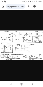
There is a 20K resistor dropping B+ from 310V to 225V(B+2)
That would give 4.25 mA?
Based on that, if I change the 20k resistor to 15K will that bump the B+2 voltage to 246V…Putting 192 V on the plate after the 27K plate resistor?
Did I do this right?
if I haven’t screwed this up yet, will the other voltages rise proportionally leaving the same bias on the 6SN7 tube?
Looking at schematics posted in my first post.
There is a 20K resistor dropping B+ from 310V to 225V(B+2)
That would give 4.25 mA?
Based on that, if I change the 20k resistor to 15K will that bump the B+2 voltage to 246V…Putting 192 V on the plate after the 27K plate resistor?
Did I do this right?
if I haven’t screwed this up yet, will the other voltages rise proportionally leaving the same bias on the 6SN7 tube?
Hmmmm. No analyzer no simulator software. I was hoping for a nudge in the right direction.
I totally get it. This is certainly old territory to most here.
Guess I’ll give it a go, and do some measurements with the multimeter, check the bias, and see if I can plot out the new curve and compare. Mostly just have a listen if nothing is too far out.
Somebody a lot more knowledgeable in this likely laid this out the way it is for a reason. Maybe the constraints of the transformer on hand. Who knows. Maybe they just like the way it sounds. I certainly do. So not expecting much, can always put it back as it was.
If this works reasonably well, I will tackle the plate resistors to see if I can increase the swing a little. Still wrapping my head around the overall effects of this, impedance, and the amperage. A lot of moving parts. A good exercise and much more fruitful than just reading the book.
Last edited:
Changing the 20k resistor to 15k will raise the B+ on both 6SN7 plates.
But how much depends on a couple of factors:
The plate impedance, rp, of the 6SN7 with the low current that you have might be 9k Ohms.
You would think that increasing the B+ by 10Volts would increase the plate current by 1.1mA (10V / 9000 Ohms).
The extra 1.1mA will cause more voltage drop in the plate load resistors.
And the increase in plate current will cause more cathode current to flow in the self bias resistors, so there will be more bias volts.
Just for fun,
First try 15k, measure the plate voltages, and the cathode self bias voltages.
Then try 10k, and see if gets the plate voltage and bias voltage you want (This might be more like you were planning).
Otherwise, you have to look at the 6SN7 plate curves of plate current, plate voltage, and bias voltage, and figure it from there.

Yeah, there's not an algebraic solution, because the valves' current draw isn't like a simple resistor (sorta/kinda close, but not exact). Fortunately, it really doesn't matter much. More voltage is more better. If you have adequate decoupling, you want as much B+ as possible, thus as small a dropping resistor as possible. Decoupling can be maintained by making the B+ bypass caps larger and/or by dividing the resistor into two (or more) parts with another bypass cap in between.
An exact answer would require an iterative process of taking an estimated total current drain, drawing loadlines for both valves, finding actual current draws, calculating new B+, and drawing new loadlines, etc. Spice would do this for you, but the gig isn't all that critical. I'd personally do it like 6A3sUMMER suggests, try a dropping resistor, maybe try another one.
All good fortune,
Chris
6SN7 measurement before and after changing B2+ dropping resistor
Maybe I’m doing something wrong, but this seems ridiculously low. Is my math good? Thanks!
20K B2+ dropping resistor : B2+ = 228.4V. (B+ 313V)
1st half / 2nd half
V drop across cathode resistor (R = 467.25 ohm): 1.03V. / (R= 27.03Kohm) 55.3V
V plate to cathode: 49.8V / 117.4V
= 2.204 mA/ 0.109W. / = 2.046mA/0.24W
10K B2+ dropping resistor: B2+ = 259.6V (B+ 308.5)
V drop across cathode resistor 1.174V / 63.23V
V plate to cathode: 57.0V / 133.1V
=2.512mA/0.14W / =2.34mA/0.311W
It's certainly not ideal, but driving low mu triodes is the hard part. We've already enjoyed the easy part, where they drive the OPT with a nice low, linear source impedance, and now must pay the price - considerable and hopefully linear grid swing. That's why any driver design that arbitrarily gives away any of the available B+ is deeply suspect. I submit that in this gig cascodes, wasting 60 VDC in this case, are too extravagant. Also, not amazingly linear. At this point, study of the characteristics curves becomes really significant.
It's also not against the laws of gods or men to build a second, smaller but higher voltage, B2 supply, for best possible performance.
All good fortune,
Chris
It's also not against the laws of gods or men to build a second, smaller but higher voltage, B2 supply, for best possible performance.
All good fortune,
Chris
Something to think on. Unlikely with these mono blocks. Almost done tinkering with them, and will likely just enjoy them as is. Maybe if I build something down the road. I have learned much—mostly just how little I know!build a second, smaller but higher voltage, B2 supply
Would a transformer with both 280 V and 300 V secondaries work for such a configuration or would it be better to have two separate power transformers?
Do you have a preferred, preferably simple, but not necessarily, design for the 6SN7 when used for driving a 45 tube?
Last edited:
Based on my measurements and questionable math (3 posts back) I only got about 0.3mA increase for a 30V increase in B2+. is it likely I am doing this wrong? Are the cathode resistors (470 ohms and 27Kohms) too big? So many moving parts to keep track of! Thanks again for your support.You would think that increasing the B+ by 10Volts would increase the plate current by 1.1mA (10V / 9000 Ohms).
I mis-spoke above; that isn't a cascode, but it has the 60 VDC penalty of a cascode, of DC coupling. It's the DC coupling that's the issue, which was a fashion darling in the 1990s.Would a transformer with both 280 V and 300 V secondaries work for such a configuration or would it be better to have two separate power transformers?
Another transformer wouldn't be needed, but separate rectifiers, preferably semi-con, and filtering would be needed. We don't do this today because commercial designers didn't do it in the Kennedy administration, and we can't possibly improve on their cost-constrained, yet hallowed, work. 300 VAC should get you close to 400 VDC at the low currents needed for drivers alone. And with great decoupling.
You may have enough source signal voltage available to get by with a single driving stage. Many would argue that this is the best choice, if possible, and others would argue that two optimized stages with feedback around them is a better driver for the capacitive load of the output valve's grid. If you really have lots of available source signal, you could use the two halves of your 6SN7 as a differential input, which would have its own advantages dealing with the cold cruel external world. Or they could be parallel, for extra driving current, but at the expense of higher input capacitance (which must be driven). Plenty of application specific options.Do you have a preferred, preferably simple, but not necessarily, design for the 6SN7 when used for driving a 45 tube?
Simplest would be to capacitor couple the existing two stages, to regain your wasted 60 VDC, and to optimize the driving triode's loadline.
All good fortune,
Chris
Rob7,
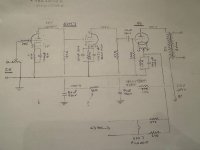
I forgot that the cascade (not cascode) input and driver tube are DC coupled (your schematic in Post # 1).
A single 6SN7 stage with the right plate load and cathode self bias resistor with bypass cap would give a gain of perhaps 15, and lots of bias voltage;
and give a linear peak to peak voltage swing of about 80% x the new higher bias voltage x 2 x 15.
Or, change the circuit to use RC coupling between the input and driver stage. That lets you use some real current in each 6SN7, lots of plate volts, lots of gain, and good linear peak to peak voltage swing. Just change the resistors for the 6SN7 cathodes and plates, and you will be there.
I seem to remember a good amplifier that used the 6SN7 in Cascade, Not Cascode. If I remember correctly it was Herb Reichert's "Flesh and Blood". There was no negative feedback. It had enough drive for a 300B, so it should work very well for a 45 tube.
For those who are afraid of RC coupling, and capacitors in general, I would like those who fear caps, to use all DC coupling, battery bias, and battery B+.
Then report back to me with the difficulties you have, how practical it is, and how good it sounds.
Or instead of batteries, just use giant non-electrolytic caps everywhere (I hope you start with real large chassis, or use a high pass filter at the amplifier input to cut off real low frequencies so you can use less capacitance for the B+ plastic caps.
The 6SN7 has fallen from favor in many peoples eyes; but I bet most everyone who built a real Flesh and Blood 300B amplifier either is still listening to it, or have sold it to someone else who is still listening to it.
Just my rambling thoughts late at night . . .
Last edited:
Thanks, Chris and 6A3s. Seems you are both leaning toward capacitor coupling or just using half of the tube.
I have barely wrapped my head around the workings of the individual triodes and measurements. The interaction between the two stages is still unclear.
Should I be targeting the volts/amps from the tube data sheet as a starting point?
Class A1
Unit 1: 90V/10mA, Unit 2: 250V/9mA
Will see if I can find Reichert’s schematic.
I also did see one schematic using half the 6SN7. Did recommend a preamp which I’m trying to avoid. Hope I can find it again.
A single 6SN7 triode and 45 has enough gain if:
You have a CD player with lots of DAC full scale output voltage (most of them have 2.1Vrms; 3V peak).
And . . .
You have to have very efficient speakers.
But listening to a typical David Chesky produced CD that peaks out at -20dB full scale, is only 0.3V peak); so you will need more gain.
*** So, for more gain from a two stage amplifier, you need: 1. A different higher u (mu) triode; 2. triode wired pentode model that has high effective u (mu); or 3. A pentode wired pentode.
There are lots of thread examples of 1. to 3. above.
Just make an initial decision of which one of the Three, and several members will find some examples for you (and then if you do not like that, pick another of the Three, and ask again).
Once built and listened to, you can always modify to another of the above topologies.
Just watch, I bet some respond to this ***, before you even ask.
Have Fun deciding, building, and listening!
Thank you! Will look into all of the above. hoping others will chime in as you said!
Any thoughts on the 6SN7 in cascode , as used in 300B modded “Morrison”, for the 45—with appropriate power transformer?
Any thoughts on the 6SN7 in cascode , as used in 300B modded “Morrison”, for the 45—with appropriate power transformer?
Last edited:
Thank you! Any personal experience or thoughts with this design?Flesh & Blood schematic
Results of changing out 20K (B2+) with 10k
I did the math on the biasing on earlier post. I believe I did it right, and if so, the triodes are biased extraordinarily cold. Maybe some further resistor changes will help both this and the voltages.
A few questions.
1. What is the likely reason the designer put the 33K resistor (arrow) there instead of just increasing the plate resistance on the first section? (Possibly too much voltage swing?). Any thoughts on reducing the value of the resistor?
To what value?
How about eliminating it altogether?
2. If I reduce or eliminate that resistor, what are the effects on the bias on the second half?
Should I:
a) increase the 47K plate resistor accordingly to keep the voltage relative to the cathode on the second half the same?
Or:
b) decrease the value of the cathode resistor on the second half to bring the cathode voltage up to compensate.
Or:
c) some combination thereof?
Looking for recommendations on specific voltages along with cathode and plate resistor values to get there. Not to forget about the 33K resistor and what I should do with that and it’s effect on the voltages for the first half.
Attachments
Last edited:
Results of changing out 20K (B2+) with 10k

A few questions.
1. What is the likely reason the designer put the 33K resistor (arrow) there instead of just increasing the plate resistance on the first section? (Possibly too much voltage swing?). Any thoughts on reducing the value of the resistor?
To what value?
How about eliminating it altogether?
2. If I reduce or eliminate that resistor, what are the effects on the bias on the second half?
Should I:
a) increase the 47K plate resistor accordingly to keep the voltage relative to the cathode on the second half the same?
Or:
b) decrease the value of the cathode resistor on the second half to bring the cathode voltage up to compensate.
Or:
c) some combination thereof?
Looking for recommendations on specific voltages along with cathode and plate resistor values to get there. Not to forget about the 33K resistor and what I should do with that and it’s effect on the voltages for the first half.
- Home
- Amplifiers
- Tubes / Valves
- 45 type SET build need assist