Hi
I think the plate tension of the 1st stage needs to be reduced. Because with direct linked, there won't be enough tension margin for the 2nd stage
If you encrease U for de 1er stage (33K become 0), saturation will come faster in de second stage and less drive available for power stage.
Yan
I think the plate tension of the 1st stage needs to be reduced. Because with direct linked, there won't be enough tension margin for the 2nd stage
If you encrease U for de 1er stage (33K become 0), saturation will come faster in de second stage and less drive available for power stage.
Yan
Thanks Yan.
I’m very new to this, but your explanation makes sense.
Also, dropping the first resistor from 20 K to 10k already has decreased the 45 plate voltage slightly.
it is very difficult to tell without proper measuring equipment, but my gut feeling is the amplifier sounded more engaging before changing the first resistor to 10K. I may go back to 20 K and listen again. It’s likely that the original designer had more knowledge and better equipment available than myself.
The more I tinker, the more I end up back where I started. A fun learning adventure.
I wouldn't want this to be read as being harsh or dismissive, but my strong feeling is that undocumented Internet Lore, from a small sampling of strangers, has little or no validity. For example, I have a particular way that I would design that amplifier - why should you trust my judgement? Not for my good looks, for sure. It's a natural part of any learning process to sample others' experiences to get your feet wet, but this needs to be paired with a parallel process of studying fundamentals, enough to at least weed out others' errors, and there will be plenty of errors in a public technical forum. Also, and more insidious, are a lot of untested (or worse, improperly tested) opinions presented as fact. For example, folk waxing eloquent about the sound of coupling capacitors having never even attempted a blind test. It's worse because it's not just invalid, but deceiving because presented as fact. Lore, even here, is a weak sister to one's own understanding of fundamentals.
In this case, the answers that you're seeking are found in the valves' characteristic curves, anode-cathode voltage vs. current with fixed grid voltages. Print some on paper and practice drawing loadlines. This will tell you everything you need to know about amplifiers in the large middle range of frequencies, and you can modify it for very low and very high frequencies as you progress. This can be done on a screen, but it's annoying - use real paper, like the saints intended, and colored pencils!
All good fortune,
Chris
ps: I know you'll want to skip this first step, but there it is.

Thanks Chris. Good advice. I actually have traced out the operating points of this design, based on Rob Robinett’s tutorial. A good learning experience. Yet having absolutely zero background in this, not everything sticks the first time around I suppose. Nor did the process make 100% sense to me. But just like everything, I gained some knowledge…just as I do from these discussions, my questions here, my books and a little experimenting with a soldering iron. A little bit at a time. Not gonna pick up the guitar and be playing like Barney Kessel the next day.
Last edited:
https://www.diyaudio.com/community/threads/has-anyone-tried-a-12au7-to-6sn7-adapter.278786/
This guy wouldn’t know an operating point or bias from a bag of rocks, nor does he have any interest in learning such. (no reflection on him, just another guy trying to do a quick mod) He asks very general questions about a cheap Chinese knock off and gets excruciatingly detailed explanations, spice modeling and diagrams along with exact resistor and capacitor values.
I understand and comprehend almost all of the advice given to him. He did not…and readily admitted such.
I draw out the schematics and take detail measurements. I put forth a few questions to validate my book learning and try to increase my knowledge. None of which he did. All I get back is I is “read the book”. Granted, I have a long way to go but I have studied this stuff.
I’m not expecting the detailed response this guy got, but to get absolutely nothing is a little disheartening.
Just a little “wine” to enjoy with some cheese over the Christmas holidays! Best to all
Last edited:
Very interested in seeing how this project works out for you! I purchased a Sony TC500a that I was planning on harvesting the Coral Holey Basket speakers from, and then I discovered that the transformers are well regarded. Planning to build something with them, and I’m trying to decide on what tubes to work with (1626, 45 or 2A3) and what schematic to implement.
As it stands, I’m leaning towards a 45. And because of the transformer and its secondary’s, I want to use a 6AX5 rectifier. That’s how I came across this thread.
There is a JE Labs schematic that uses a 5Y3 that I’m thinking shouldn’t be too difficult to rework with the 6AX5.
Look forward to seeing how this gets completed!
P
Quite possibly the output transformers in my mono blocks came from this Sony.purchased a Sony TC500a
Despite the naysayers of the design of these mono blocks, they sound fabulous. Indeed, the direct couple design and operating points are crazy similar to a very popular 2a3/12au7 which was highly praised and currently in the primary system of a renowned tube enthusiasts… his design work was even recommended to me in an earlier post here.
I also own this amplifier of which he spoke so highly in a recent Stereophile review and it sounds wonderful! Yet, since I acquired these mono blocks, it has been gathering dust.
In my continuing research, I have discovered that these mono blocks are very likely from Alan Eaton.
Some hang everything on their Intel powered audio analyzer and theory—which drove design away from the SET in the first place. While essential tools, none come close to the raw processing power of my personal teraflop audio analyze… it sits between my ears
Last edited:
Was looking at the schematic, the tube complement and the ratings on the secondaries, I was wondering if the transformers were indeed from a Sony.
Wondering if you have any photos of the inside of the amp?
Wondering if you have any photos of the inside of the amp?
I love Stephe’s work. Keep in mind her problem with the so-called Morrison design was the front end was clipping before the power tubes.And I’m going to look at JCM’s design and what Stephe did to it at Skunkie.
If you are not running the amp to clipping, does this matter? You decide.
I have not the equipment to measure, but I’m fairly confident this would not be a problem with a 45 tube.
Certainly a technical argument could be made against this design. However, there is a reason designers went with the direct coupled. There is a reason it became very popular in the mid 90s. With the right speakers, they sound good. Very good.
If you’re looking for theoretical technical perfection, SET is not the place anyhow.
The amplifier to which I was referring above, which I own and built, is the Elekit 8900. It comes with the schematics and designed voltages and with test points. I have tested the voltages on both amps.
The 8900 uses a direct coupled 12AU7 driver with remarkably low operating points—similar to the AE amp. Look up the reviews. My personal preference is the AE mono blocks. The AE amplifiers have been around a lot longer than the 8900. (Not so sure I would be inclined to go with the single integrated AEs)
For comparison, I also have the Elekit S8600, Luxman MQ-88usE, and had a Raven Osprey.
My big gun system consists of Mark Levinson, 536 mono blocks, 523 pre-and 802 D3 speakers. Hard to match the technical chops of that system and , believe me, it sounds great! But, more often than not, I find myself listening to the 45 mono blocks.
Last edited:
Been following her on YouTube for a while now.
Like you, I don’t really have any test equipment. Just the basics.
Direct coupled and transformer coupled have become things of interest to me also as of late. Likely because of all the info I’ve come across about early WE amps and how the first cinema sound systems were designed.
Think I’ve settled on a schematic for this build, if I don’t commit to something, I’m going to end up changing my mind 100 times and nothing gets done, nothing learned.
I had watched Skunky’s entire 300B series before I acquired these amps.
When I first unraveled the design my heart sunk, realizing it was so very similar to the maligned JC Morris design. Didn’t matter what my ears said… It couldn’t sound good… The “experts” said so.
Somewhere, likely in Japan, somebody through experimentation, bread boarding, and listening fell upon this design and liked it very very much. Likewise did many others. Thus it’s raging popularity in the 90s.
Somewhere along the line the experts said it’s technically wrong, so it can’t sound good… all the listeners have to be wrong—“why…just look at those crazy operating points of the driver!”
Every additional capacitor, especially one directly in line with the music signal, will have some effect on frequency and phase. Negligible….lesser effect than running the tubes at an odd operating point? Who knows? It all adds up.
That’s part of what led me on this quest of searching for a better design.
Bottom line, a few cap upgrades, and taming the filament voltage, and I absolutely love the sound of these amplifiers.
Herb, Reichert a noted tube amplifier designer in his own right, seems to have an affinity for the DC design based on his own reviews of the very recent 8900.
To my original premise, it ultimately comes down to the most sophisticated quantum teraflops capable audio processor in existence. Your brain. I absolutely love these amplifiers. You can see in my above post, I have plenty to compare to.
To your point… Yep. You got to decide and make a move!
Last edited:
There are lots of pictures of the AE amplifier internals online.transformers were indeed from a Sony.
If you are planning on an integrated stereo, I am not sure the power transformer in my mono blocks would be up to the task of running two channels.
Many, much smarter than me, say plenty of headroom from the power transformer makes a difference in the sound signature.
JCM was part of the NYC Triode Mafia. The Feral Eye 2A3 PP (designed by then) is another amp I’m wanting to have a stab at. He’s designing for Silbatone now.
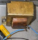
PT secondary look like 60 mA. As I recall, the draw is about 40 mA on these mono blocks. Maybe not best choice for stereo?Wondering if you have any photos of the inside of the amp?
These amplifiers have a separate hammond filament transformer. Sadly, it has 115 V primaries and puts out considerably more than the specified voltage. I have added dropping resistors to rein it in.
EML tubes has a technical article discussing filament voltages. References a military study citing a 10% decrease in filament life for each one percent above or below the spec voltage. The typical 5% tolerance would reduce the life by 50% if accurate. Too low is actually worse than too high when you look at the graphs supplied. A good read.
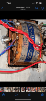
First photo is PT, second photo is output transformer. Tamura 5k in 8 ohms out. Simple with no extraneous windings. Perfect.
As for JCM design, some debate as to who actually designed this 300 B scheme. Quite possible it was somebody from Japan and JCM just published it. 🤷
Attachments
Last edited:
To clarify, my earlier statements.The 8900 uses a direct coupled 12AU7 driver
The driver tube half’s are direct coupled to each other…no capacitor.
The power tube is NOT direct coupled—It is capacitor coupled to the driver.
The direct coupled first and second stage biased as low as the first stage is, results in a very poor performing amplifier. This has been discussed by Stephe (300b review mods)in her redesign using a Cascode front end, my redesign using capacitively coupled common cathode stages(Ebay 300B PCB), as well as many others.Results of changing out 20K (B2+) with 10k
View attachment 1249688
A few questions.
1. What is the likely reason the designer put the 33K resistor (arrow) there instead of just increasing the plate resistance on the first section? (Possibly too much voltage swing?). Any thoughts on reducing the value of the resistor?
To what value?
How about eliminating it altogether?
2. If I reduce or eliminate that resistor, what are the effects on the bias on the second half?
Should I:
a) increase the 47K plate resistor accordingly to keep the voltage relative to the cathode on the second half the same?
Or:
b) decrease the value of the cathode resistor on the second half to bring the cathode voltage up to compensate.
Or:
c) some combination thereof?
Looking for recommendations on specific voltages along with cathode and plate resistor values to get there. Not to forget about the 33K resistor and what I should do with that and it’s effect on the voltages for the first half.
The bias point of the first stage results in high distortion at low output levels. I did not see this at the low levels my speakers could be driven with, until I cranked it up.
This is a very poor performing design.
I think Stephe's mods are a better solution overall, and suggest you read her thread as it is a great summation of the redesign process.
My 2c
Appreciate the input. I have watched her videos repeatedly and I’m inclined to agree with much of what she says. But again, she is driving a 300 B to clipping in her tests. Her concern is that the front end is clipping before the power tubes. Quite legit if you’re going to listen at those levels.think Stephe's mods are a better solution overall
The 45 is easier to drive and much more likely to clip prior to this driver design so a direct comparison is difficult at best.
She is using marginally efficient multi driver speakers (efficiency, highly exaggerated by the manufacturer) with crazy impedance swings and phase shifts that accompany such configurations. Any phase shift she is has added with her design is likely below the levels induced such speakers and goes unnoticed.
Unlikely you are going to reach levels anywhere near where she is testing this amplifier with even reasonably efficient single driver speakers.
The design she is using is known to have its own problems… Mostly phase shift.
I’m inclined to believe the magic from SE triodes is more than just second order harmonics. Our brains are highly attuned to phase shift. That’s how we can tell if we are in the great outdoors or inside a cave, even with our eyes shut. Some people blind from birth can even echo locate to a highly detailed level.
There is no avoiding phase shifts in the system, but a little here and a little there are cumulative. The less the better.
As for the low operating points of the driver section, you can argue that with Herb Reichert, a well -known tube amplifier designer who touts the magic of the EK 8900–which also uses direct couple 12AUX driver halfs at unusually low operating points. This is in his primary listening rotation.
The tech heads have decided this design didn’t make sense…and maybe it doesn’t. Maybe it’s not enough for the 300B. But with these 45 tubes… Damn, it sounds good! Read back five or six posts, I’ve already covered this and the equipment I have to compare it to.
Last edited:
The argument against sloppy driver stage design is that it wastes output stage headroom at the cost of output stage operating points that could have been moved to both a more linear and less power consuming region, and for no benefit.
And I reject all appeals to Gurus - pants on one leg at a time, like that.
All good fortune,
Chris
And I reject all appeals to Gurus - pants on one leg at a time, like that.
All good fortune,
Chris
- Home
- Amplifiers
- Tubes / Valves
- 45 type SET build need assist