That is generally recommended to supply voltage to the high-side of the 21844, not to the positive rail. A 9v battery with very low current capacity is all that's needed. The 1 ohm resistor is there in case there is voltage present on the 21844 (there should be none). It should prevent the 9v battery from exploding.
So to connect the battery, I decided, after reading this thread: "DD Z2 bursts output transistors".
I have 4 218844 on the board. Should I connect the battery in turn to each of them?
Maybe I misunderstood something.Battery negative terminal to negative terminal of negative rail cap.
Battery positive terminal to positive terminal of negative rail cap.
Is that what you did?
I have 4 218844 on the board. Should I connect the battery in turn to each of them?
In both (very different situations) I used a standard 9v battery (MN1604 type).
What have you done in repairing the amp?
What sort of problem are you having where you need to use a battery to check drive signals?
What have you done in repairing the amp?
What sort of problem are you having where you need to use a battery to check drive signals?
After my last post (12.03.18), I once again replaced all 21844 and installed all the output transistors. Now I want to check the impulses on the gates.
This is my first quote:
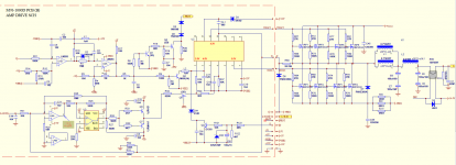
Hello. I work with amplifier 4000.1. Driver board, part of the circuit and oscillogram attached. The problem is that the meander disappears at the output of LM311 when I solder the output 24N40F. Changed LM311, TL 072 and IR21844. What would you recommend?
There is a high-value feedback resistor that connects between the output of the amp to the input pin of the drive board. Desolder and lift one end of it. Does that restore the drive signals that you had before you installed the FETs?
This should not be done with the rectifiers in the circuit. I'm assuming that you have them out of the circuit.
You may need to add a 10k resistor between pins 1 and 2 of the TL072.
This should not be done with the rectifiers in the circuit. I'm assuming that you have them out of the circuit.
You may need to add a 10k resistor between pins 1 and 2 of the TL072.
Last edited:
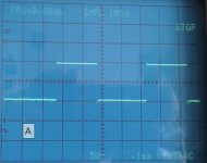
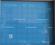
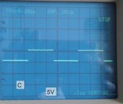
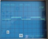
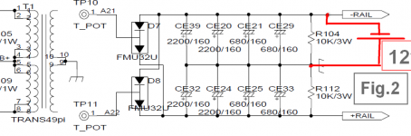
Removed rectifier diodes and resistor 240K. Here's what he measured::
Attachments

Last edited:
If you have less than 1v of drive into pin 1 of the 21844, you need to use an isolated power supply (9v battery will work) to connect across the negative rail caps so the drive circuit driving pin 1 can develop better voltage.
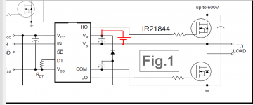
It will connect across the negative rail caps. I don't know what sort of 12v battery you have but if it's something capable of high current, insert a current limiter of some sort. A 12v lamp of some sort would be a good choice.
It's drawn correctly in figure 2. The positive terminal of the battery goes to the positive terminal of the negative rail cap.
The scheme of my AMP largely coincides with this scheme (only here instead of + - RAIL, denoted + VCC2 and - VEE2 and I have 4 pieces 21844).
Now in my AMP, diodes, forming + -RAIL are extracted. But -RAIL + 12V, with a separate transformer winding, after rectification and amplification are fed into the circuit, including on 21844.
Perry, are you sure that to include a 9V battery between GROUND and -RAIL (-VEE2) is the right solution?
Now in my AMP, diodes, forming + -RAIL are extracted. But -RAIL + 12V, with a separate transformer winding, after rectification and amplification are fed into the circuit, including on 21844.
Perry, are you sure that to include a 9V battery between GROUND and -RAIL (-VEE2) is the right solution?
Attachments
- Status
- Not open for further replies.
- Home
- General Interest
- Car Audio
- 4000.1