Now I have one IC 21844 and one transistor 24n40f in each LO and HO sides.
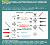
Check 21844. The arrows in the figure mean "Measure between these pins" or "Measure first in one polarity, then change the probes in places"?
Check 21844. The arrows in the figure mean "Measure between these pins" or "Measure first in one polarity, then change the probes in places"?
The arrows show which pins to measure between. What's important is that all ICs measure the same.
All 4 ICs are installed? Or only two ICs installed?
All 4 ICs are installed? Or only two ICs installed?
Now there is only one IC 21844. I want to achieve that everything works well with one chip, then I'll add others. Because already 10 output transistors are damaged.
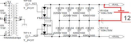
If I measure the resistance between 11 and 12 pins with the polarity of the probes as in the figure, it shows 30 KΩ, and if the negative probe is 12 pin, it sometimes shows 4.7 KΩ and sometimes 17 KΩ.
If I measure the resistance between 11 and 12 pins with the polarity of the probes as in the figure, it shows 30 KΩ, and if the negative probe is 12 pin, it sometimes shows 4.7 KΩ and sometimes 17 KΩ.
Similar measurement between the 5 and 6 pins. "+" probe on the 6th pin - 24 Kohm. And if "-" probe on 6 pin, sometimes 17 Kohm, and sometimes - 4.7 Kohm.
When measuring the voltage on regulators, it's often better to place the black probe on the regulator's ground terminal and the red alternately on the other two terminals. Here it didn't really make a difference.
Confirm that the 12v is reaching the driver board pads by reading across pins'pads 5 and 7 (black probe).
Re: post 26.
Can you lift either pin (11 or 12) and measure the resistance them with out the connection to the board?
Confirm that the 12v is reaching the driver board pads by reading across pins'pads 5 and 7 (black probe).
Re: post 26.
Can you lift either pin (11 or 12) and measure the resistance them with out the connection to the board?
Between 5 and 7 pin's IC 21844 there are 12 volts.
If I measure the resistance between 11 and 12 pins with the polarity of the probes as in the figure, it shows 8 MΩ, and if the negative probe is 12 pin, it sometimes shows 110 KΩ and sometimes 18 KΩ
If I measure the resistance between 11 and 12 pins with the polarity of the probes as in the figure, it shows 8 MΩ, and if the negative probe is 12 pin, it sometimes shows 110 KΩ and sometimes 18 KΩ
Between 5 and 7 pin's IC 21844 there are 12 volts.
If I measure the resistance between 11 and 12 pins with the polarity of the probes as in the figure, it shows 8 MΩ, and if the negative probe is 12 pin, it sometimes shows 110 KΩ and sometimes 18 KΩ . 11 pin - in the air.
If I measure the resistance between 11 and 12 pins with the polarity of the probes as in the figure, it shows 8 MΩ, and if the negative probe is 12 pin, it sometimes shows 110 KΩ and sometimes 18 KΩ . 11 pin - in the air.
Hi. I again decided to deal with this amplifier. I want to remove the rectifiers and connect a 12v lead battery to the high-side. What is the minimum capacity for this battery?
How battery should be connected? As in the picture?
There is no misprint, exactly 1 OM? Calculation shows that with this resistance, the initial charge current of the capacitors will be 12A.If you use a 9v battery, you should insert some sort of over-current protection. A 1 ohm 1/8w resistor would work. A 1 amp fuse should also be OK.
How battery should be connected? As in the picture?
Attachments
- Status
- Not open for further replies.
- Home
- General Interest
- Car Audio
- 4000.1