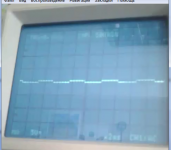
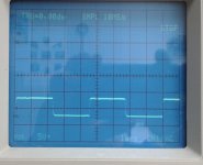
The pulses on the gates of all 24N40F are in the first figure. As can be seen, the average value of the pulses is not 0 Volts, but, approximately, minus 4 Volts. So it should be?
I sent a musical signal to the input of the amplifier - the duration of the pulses on the gates began to change.
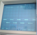
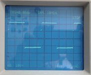
Returned the feedback resistor. The pulses on the HI side disappeared, and on the LO side - in the second figure.
Can I test anything more without rectifying diodes?
I sent a musical signal to the input of the amplifier - the duration of the pulses on the gates began to change.
Returned the feedback resistor. The pulses on the HI side disappeared, and on the LO side - in the second figure.
Can I test anything more without rectifying diodes?
Attachments
Could be used but too hard to replace if damaged.
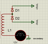
You can make your own low voltage supply by winding about 5 turns around one of the power transformers. You want to use whatever number of turns that give you a ±15v output on the windings.One end of the winding will go to the secondary ground. The other will go to two rectifiers (should be high-speed or fast recovery types). The winding will go to the center of the two rectifiers. The output of the two rectifiers will go to the rail caps.
I strongly recommend that you use a current limiter between the winding and the rectifiers to protect various components. In the attached photo, you see an 1157 lamp being used. An automotive headlamp or even a dummy load resistor can be used. The lamps are good because they immediately alert you to a problem.
Attachments

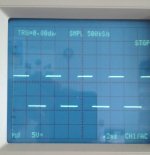
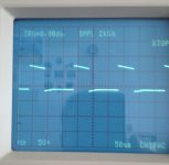
Wrapped 2 turns. Through "HER107" filed + -12 volts to the "+ -Rail". The feedback resistor is set. Fig. 1 - the pulses on the first "pin" of all 21844. Fig.2 - the gates of the transistors of the lower side. Fig.3 - gates of transistors of the upper side. What's next?
Attachments

I do not understand your question. Rectifier diodes are extracted. How can an amplifier produce audio?
It will run off of the winding that you added. It will not play loud but should play and allow you to check the drive signals. The 10k resistor (if you have one installed on the TL072) needs to be removed and the high-value feedback resistor (if removed) must be back in the circuit.
A quiet sound is played back. The signals on the gates are the same in amplitude as in post 72. Their duration varies according to the musical signal.
I'd expect about 80kHz. It may be higher at higher voltage.
Were you having problems with the outputs failing (for no obvious reason) or other problems, initially?
Were you having problems with the outputs failing (for no obvious reason) or other problems, initially?
- Status
- Not open for further replies.
- Home
- General Interest
- Car Audio
- 4000.1