Hey CyberPit-San
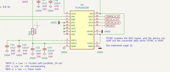
Why do you have MP10 and MP11 as Output??
The Slave channel is set to determine which input it will be named as in the input selector ... right?
And for the ADCs, I would have thought that no matter how you configure the DSP, if it gets the right clock signals then it would just free flow output data !?!? .... but the data line is dead
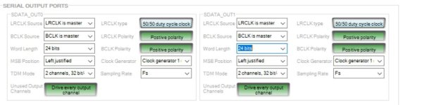
Yes 😍 ... I have data out on the DAC and a nice sine on the output 🙂 👍
Seems my output regs where not correct
Seems my output regs where not correct
Attachments
Last edited:
Member
Joined 2018
Tried to measure on the I2C port while writing to the EEPROM ... and there is lots of signaling. So it is NOT choosing the right port for writing to the EEPROM ...
Also just realized that PCM1802 needs a 5V psu for the analog part ..... I'm only giving it 3.3V .... Maybe this is why it is not outputting any data
Also just realized that PCM1802 needs a 5V psu for the analog part ..... I'm only giving it 3.3V .... Maybe this is why it is not outputting any data
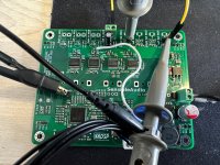
Giving PCM1802 5V on the analog psu made the difference, and now it is outputting data.
Damn, why didn't I realize this in the design phase 😱😵😢
Solved by lowering the output voltage of the TSP5430 to 5V and using this. Not optimal for noise, but at least it now works.
Funny thing is of course that I had chosen the output of the SMPS to 8V in order to use a following 5V LDO!!!!
... begining to look like a version 2 of the pcb ......
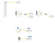
Testing ipput and output, via a loop back.
Creating a 2kHz tone in DSP, outputting on DAC0, Reading it with ADC0 and Outputting on DAC1 ... it all works
Still no progress with EEPROM ....
Creating a 2kHz tone in DSP, outputting on DAC0, Reading it with ADC0 and Outputting on DAC1 ... it all works
Still no progress with EEPROM ....
Attachments

Ahhhhggggg 😵😱.... Not sure what I have been thinking, but even stating here I am using a 25LC512-I/SN EEPROM, I was still thinking about a 1Mbit size!!! .... corrected the settings for a 512kbit, 128 byte page size with 2 address bits, and it all works.
The thing about signals on the bus not being visible, was due to it's burst nature, and the scope not being set well enough, so didn´t see it

But now it boots as is should 👍😊
The thing about signals on the bus not being visible, was due to it's burst nature, and the scope not being set well enough, so didn´t see it
But now it boots as is should 👍😊

Is there "more finalized" version of this than the one in post #107? 🙂 I've been looking for a good cheap analog DSP for a while but managed to ignore your creation for some reason... would love to order some of these from JLCPCB or similar! Is the PCB still 100x80mm? Have you by any chance measured the performance?
I'm sharing all my learnings here including schematics 😉
Not sure I'll just share the PCB design though ...... unless someone is also willing to share some of the development cost 😉
Too much (real) work, so haven't had time to measure yet
Not sure I'll just share the PCB design though ...... unless someone is also willing to share some of the development cost 😉
Too much (real) work, so haven't had time to measure yet
Hi Baldin,
You have made some nice progress, congrats.
I would also be very keen to see some measurements. On the Octavia board we saw some higher harmonics on the dac output and it would be very interesting to see if you measure the same since you are using the same DAC, if I am not mistaken.
BR
Ludwig
You have made some nice progress, congrats.
I would also be very keen to see some measurements. On the Octavia board we saw some higher harmonics on the dac output and it would be very interesting to see if you measure the same since you are using the same DAC, if I am not mistaken.
BR
Ludwig
Hi Ludwig
Yes measurements are next point.
Have been tied up in work so have had no time for it yet.
Maybe in the weekend 😉
.... do not have a ready to use measurement setup, so might take a bit of time to get right .... but need to do that anyway 😉
Yes measurements are next point.
Have been tied up in work so have had no time for it yet.
Maybe in the weekend 😉
.... do not have a ready to use measurement setup, so might take a bit of time to get right .... but need to do that anyway 😉
- Home
- Source & Line
- Digital Line Level
- 4 in 8 out DSP using ADAU1652